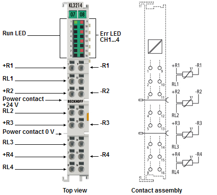
Contact assignment and LEDs
Contact assignment
Terminal point | No. | Comment |
|---|---|---|
+R1 | 1 | Input +R1 |
RL1 | 2 | Input RL1 |
+R2 | 3 | Input +R2 |
RL2 | 4 | Input RL2 |
+R3 | 5 | Input +R3 |
RL3 | 6 | Input RL3 |
+R4 | 7 | Input +R4 |
RL4 | 8 | Input RL4 |
-R1 | 9 | Input –R1 |
n.c. | 10 | reserved |
-R2 | 11 | Input –R2 |
n.c. | 12 | reserved |
-R3 | 13 | Input -R3 |
n.c. | 14 | reserved |
-R4 | 15 | Input -R4 |
n.c. | 16 | reserved |
LED displays
LED | Display | Description |
|---|---|---|
Run | Green illuminated | Normal operation |
Off | Watchdog-timer overflow has occurred. | |
Error | red illuminated | The respective channel is affected by a short circuit or broken wire. |
Off | The resistance is in the valid range of the characteristic curve. |