Contact assignment and LEDs
| |
Risk of injury through electric shock and damage to the device! Bring the Bus Terminals system into a safe, de-energized state before starting mounting, disassembly or wiring of the Bus Terminals. |

KL3201/KS3201
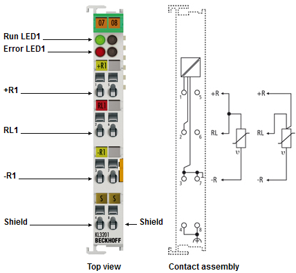
Terminal point | No. | Comment |
|---|---|---|
+R1 | 1 | Input +R1 |
RL1 | 2 | Input RL |
-R1 | 3 | Input -R1 (internally connected with terminal point 7) |
Shield | 4 | Shield, FE (internally connected to terminal point 8) |
n.c. | 5 | not connected |
n.c. | 6 | not connected |
-R1 | 7 | Input -R1 (internally connected with terminal point 3) |
Shield | 8 | Shield, FE (internally connected to terminal point 4) |
LED displays
LED | Color | Description | |
|---|---|---|---|
Run | green | On | Normal operation |
Off | Watchdog-timer overflow has occurred. If no process data is transmitted to the bus coupler for 100 ms, the green LEDs go out | ||
Error | red | On | The respective channel is affected by a short circuit or broken wire. The resistance is in the invalid range of the characteristic curve. |
Off | The resistance is in the valid range of the characteristic curve. | ||
KL3202/KS3202
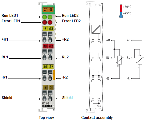
Terminal point | No. | Comment |
|---|---|---|
+R1 | 1 | Input +R1 |
RL1 | 2 | Input RL |
-R1 | 3 | Input -R1 (internally connected with terminal point 7) |
Shield | 4 | Shield, FE (internally connected to terminal point 8) |
+R2 | 5 | Input +R2 |
RL2 | 6 | Input RL |
-R2 | 7 | Input –R2 (internally connected with terminal point 3) |
Shield | 8 | Shield, FE (internally connected to terminal point 4) |
LED displays
LED | Color | Description | |
|---|---|---|---|
Run | green | On | Normal operation |
Off | Watchdog-timer overflow has occurred. If no process data is transmitted to the bus coupler for 100 ms, the green LEDs go out | ||
Error | red | On | The respective channel is affected by a short circuit or broken wire. The resistance is in the invalid range of the characteristic curve. |
Off | The resistance is in the valid range of the characteristic curve. | ||
KL3204/KS3204, KL3204-0030
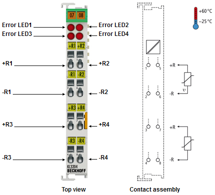
Terminal point | No. | Comment |
|---|---|---|
+R1 | 1 | Input +R1 |
-R1 | 2 | Input –R1 |
+R3 | 3 | Input +R3 |
-R3 | 4 | Input -R3 |
+R2 | 5 | Input +R2 |
-R2 | 6 | Input –R2 |
+R4 | 7 | Input +R4 |
-R4 | 8 | Input -R4 |
LED displays
LED | Color | Description | |
|---|---|---|---|
Error | red | On | The respective channel is affected by a short circuit or broken wire. The resistance is in the invalid range of the characteristic curve. |
Off | The resistance is in the valid range of the characteristic curve. | ||