Basic function principles
The analog input terminals
KL3011 and KL3012 process signals in the range from 0 mA to 20 mA
KL3021 and KL3022 process signals in the range from 4 mA to 20 mA
with 12-bit resolution (4095 steps). The terminal inputs are differential inputs with common ground. Due to the differential inputs, the terminals are particularly suitable for ground-free measurements in current loops.
Cross-currents caused by voltage differences at the input terminals do not lead to any appreciable measurement distortion up to a difference in potential of 35 V (UCM = 35 V).
The LEDs indicate the operating state of the associated terminal channels.
- green Run LED:
- On: Normal operation
- Off: Watchdog-timer overflow has occurred. If no process data are transmitted by the Bus Coupler for 100 ms, the green LEDs go out.
- red Error LED:
- On: The limit stop of the A/D converter has been reached. The current is greater than 21.5 mA.
- Off: Normal operation
Process data output format
In the delivery state the process data are shown in two's complement form (integer -1 corresponds to 0xFFFF). Other presentation types can be selected via the feature register (R32) (e.g. signed amount representation, Siemens output format).
Measured value | Output | ||
|---|---|---|---|
KL3011, KL3012 | KL3021, KL3022 | dec | hex |
0 mA | 4 mA | 0 | 0x0000 |
10 mA | 12 mA | 16383 | 0x3FFF |
20 mA | 20 mA | 32767 | 0x7FFF |
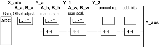
Calculation of process data
The terminal continuously takes measured values and stores the raw values of its A/D converter in register R0 (RAM ). The calculation of the correction with the calibration values takes place after each sampling of the analog signal. This is followed by manufacturer and user scaling:
The process data that are transferred to the Bus Coupler are calculated using the following equations:
Y_a = (B_a + X_adc) * A_a | (1.0) | Neither user nor manufacturer scaling is active. |
Y_1 = B_h + A_h * Y_a | (1.1) | Manufacturer scaling active: (Default setting) |
Y_2 = B_w + A_w * Y_a | (1.2) | User scaling active |
Y_1 = B_h + A_h * Y_a | (1.3) | Manufacturer and user scaling active |
Key
Name | Name | Register |
|---|---|---|
X_adc | Output value of the A/D converter | - |
Y_aus | Process data for controller | - |
B_a | Vendor calibration: Offset | |
A_a | Vendor calibration: Gain | |
B_h | Manufacturer scaling: Offset | |
A_h | Manufacturer scaling: Gain | |
B_w | User scaling: Offset | |
A_w | User scaling: Gain |
The equations of the straight line are enabled via register R32.