KL/KS2602 - Contact assignment and LEDs
| |
Risk of injury through electric shock and damage to the device! Bring the Bus Terminal system into a safe, de-energized state before starting mounting, disassembly or wiring of the Bus Terminals! |

Notice | |
Risk of device damage! Note that the use of potential separation terminals (e.g., KL9080) is necessary when planning the Bus Terminal system with different potentials on the power contacts (e.g., 24 VDC and 230 VAC)! |
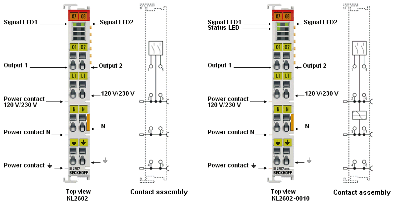 Fig.2: KL2602, KL2602-0010 - Contact assignment and LEDs
KL/KS2602, KL/KS2602-0010 - Contact assignment
Terminal point | Description | |
|---|---|---|
Name | No. | |
01 | 1 | Output 1 (relay) |
L1 | 2 | 120 / 230 VAC (internally connected to terminal point 6 and L power contact) |
N | 3 | Neutral conductor (internally connected to terminal point 7 and N power contact) |
⏚ | 4 | Earth contact (internally connected to terminal point 8 and ⏚ power contact) |
02 | 5 | Output 2 (relay) |
L1 | 6 | 120 / 230 VAC (internally connected to terminal point 2 and L power contact) |
N | 7 | Neutral conductor (internally connected to terminal point 3 and N power contact) |
⏚ | 8 | Earth contact (internally connected to terminal point 4 and ⏚ power contact) |
KL/KS2602, KL/KS2602-0010 - LED displays
LED | Color | State | Meaning |
|---|---|---|---|
Signal-LED | green | off | No output voltage at Output 1 or Output 2 |
on | Output voltage (≤ 230 VAC or ≤ 30 VDC) at Output 1 or Output 2 | ||
Status-LED | green | off | Terminal is not synchronized (relay switches without delay e.g., with DC supply) |
on | Terminal is synchronized to mains frequency |