Contact assignment
| |
Risk of injury from electric shock and damage to the device! Bring the Bus Terminals system into a safe, de-energized state before starting mounting, disassembly or wiring of the Bus Terminals! |

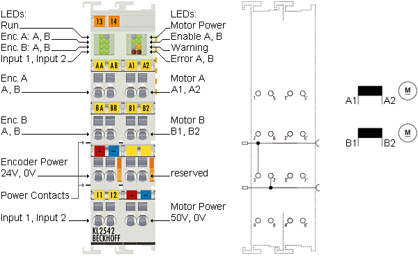
Left-hand section of the housing
Terminal point | No. | Connection for |
|---|---|---|
Encoder A, A | 1 | Encoder A, connection A |
Encoder B, A | 2 | Encoder B, connection A |
Encoder power +24 V | 3 | Encoder supply (from positive power contact) |
Input 1 | 4 | Digital input 1 (24 VDC). |
Encoder A, B | 5 | Encoder A, connection B |
Encoder B, B | 6 | Encoder B, connection B |
Encoder Power 0 V | 7 | Encoder supply (from negative power contact) |
Input 2 | 8 | Digital input 2 (24 VDC). |
Right-hand section of the housing
Terminal point | No. | Connection for |
|---|---|---|
Motor A, A1 | 1' | Motor A, connection A1 |
Motor B, B1 | 2' | Motor B, connection B1 |
n. c. | 3' | reserved |
Power Motor 48 V | 4' | Motor supply feed (maximum +48 VDC) |
Motor A, A2 | 5' | Motor A, connection A2 |
Motor B, B2 | 6' | Motor B, connection B2 |
n. c. | 7' | reserved |
Power Motor 0 V | 8' | Motor supply feed (0 VDC) |
| |
Danger for persons, the environment or devices! If the K-bus voltage (5 V, supplied via the Bus Coupler supply voltage Us) fails, the output drivers are not reset. This means that the motors are not stopped if they are in motion! |
Power contacts
The voltage Up of the power contacts (+24 VDC) supplies the following consumers:
- Incremental encoder (terminal points 3 and 7)
- Digital inputs (terminal points 4 and 8)
- Output driver of the DC motor output stage
| |
Please note the order of the supply voltages. The voltage Up must already be present at the power contacts when the K-bus voltage is switched on so that the internal circuits (output stage drivers) can be initialized. If this is not possible due to the application (supply is switched, for example, via emergency stop circuit), the terminal performs a software reset after the system starts up. If the voltage Up at the power contacts fails, this is indicated in register 0 through bit R0.14. The return of the voltage is automatically detected and an initialization is performed. |