Contact assignment and LED displays
| |
Risk of injury through electric shock and damage to the device! Bring the Bus Terminals system into a safe, de-energized state before starting mounting, disassembly or wiring of the Bus Terminals! |

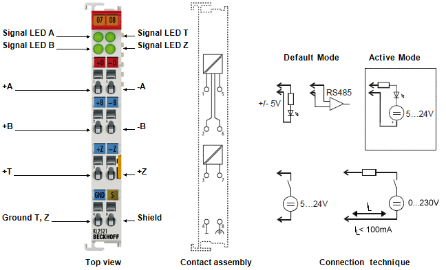 Fig.1: KL2521-xxxx - Connection and LEDs
KL2521-xxxx - Contact assignment
Terminal point | No. | Comment |
|---|---|---|
+A | 1 | Output +A |
+B | 2 | Output +B |
+T | 3 | Input T |
GND T, Z | 4 | Signal ground for the outputs |
-A | 5 | Output -A |
-B | 6 | Output -B |
+Z | 7 | Input Z |
Shield | 8 | Shield |
KL2521-xxxx - LED displays
LED | Color | Description |
|---|---|---|
Signal LED A, B | green | The four LEDs light up with active signal levels of the inputs and outputs. The illumination of the LEDs for the active frequency outputs A or B at higher frequencies can only be perceived as a glow at half brightness. When the watchdog is active (Feature.2 = 0!!!) the terminal will switch the outputs off or will output a value stored in register 35 if no new process data is transferred to the terminal within 100 ms. |
Connecting the inputs (KL2521-0000, KL2521-0024)
The optically isolated inputs are protected from overload by a current limiter. Without further external circuitry the operating voltage may lies between 5 V and 24 VDC. The GND connection is the common ground for the two inputs, T and Z. The circuit diagram shows the internal circuitry of the two inputs:
 Fig.12: Internal circuit of the inputs T and Z
Connection of the outputs
Circuit examples for output to A. The same principles apply to output B.
KL2521-0000
The outputs A and B of the EL2521 can be used in different connection modes. An integrated DC/DC converter supplies the output stage of the two channels, A and B, with an electrically isolated 5 V power supply.
- Connection to RS485/RS232 receiver
The output can be operated as RS485 or as RS232 output. The circuit generates the necessary differential signals.
 Fig.13: KL2521-0000 on the RS485/RS232 receiver
- Connection to optocoupler (without external supply voltage)
The outputs can be used for direct connection of an optocoupler. The output stage supplies the necessary output current using an internal 5 V supply voltage.
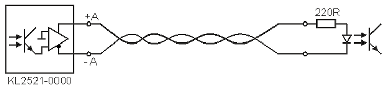 Fig.14: EL2521-0000, direct connection to an optocoupler
Connection to optocoupler (with external supply voltage)
For connection to inputs with a large input resistance, an external supply voltage (up to 24 V) can be used with the EL2521-0024 in order to create the necessary current.
 | Operation with an external supply voltage is dependent on the hardware version The operation with an external supply voltage depends on the hardware version of the terminal:
|
- KL2521-0000 up to hardware version 03
- Instead of hardware version 04 (or higher), use the special variant KL2521-0024
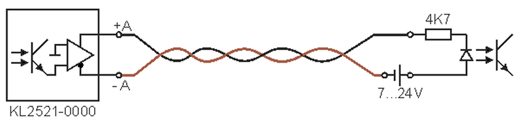 Fig.15: KL2521-0000 up to hardware version 03 - wiring with external power source
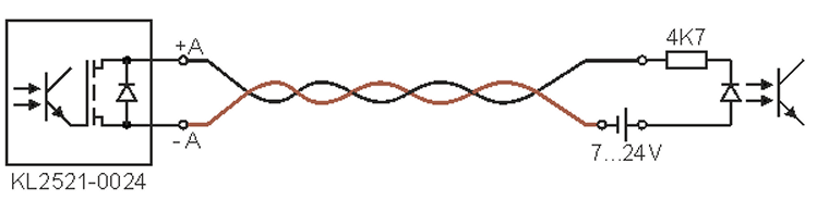 Fig.16: KL2521-0024 - wiring with external power source
See chapter Documentation issue status for the determination of the hardware version
KL2521-0024: Connection to external electronics
Note when connecting external electronics that terminal point A of the first channel and terminal point B of the second channel of a KL2521-0024 are connected to each other internally.
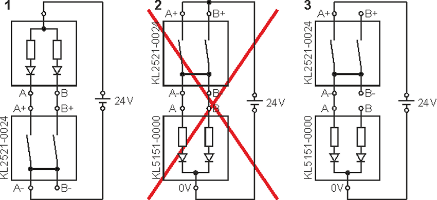 Fig.17: KL2521-0024 - connection to external electronics
This allows the dual-channel connection of external electronics if the KL2521-0024 switches the ground of the connected device as shown in example 1.
| Notes on connection to external electronics
|