Contact assignment and LEDs
 WARNING
Bring the Bus Terminal system into a safe, voltage-free state before starting mounting, disassembly or wiring of the Bus Terminals!
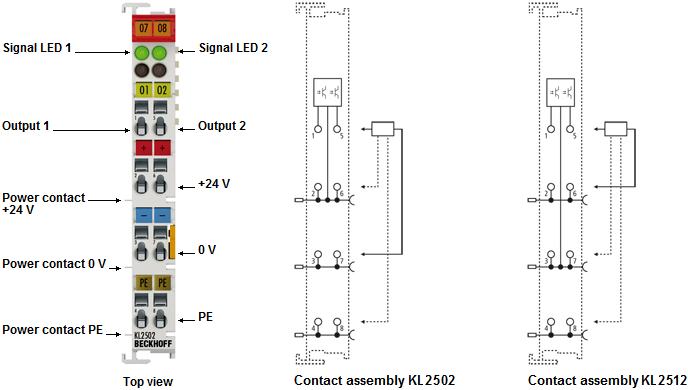
KL2502/KS2502, KL2512/KS2512 Contact assignment | ||
|---|---|---|
Terminal point | No. | Comment |
Output 1 | 1 | Output 1 |
+24V | 2 | +24 V (internally connected to terminal point 6 and positive power contact) |
0V | 3 | 0 V (internally connected to terminal point 7 and negative power contact) |
PE | 4 | PE connection |
Output 2 | 5 | Output 2 |
+24V | 6 | +24 V (internally connected to terminal point 2 and positive power contact) |
0V | 7 | 0 V (internally connected to terminal point 3 and negative power contact) |
PE | 8 | PE connection |
KL2502/KS2502, KL2512/KS2512 LED display | ||
|---|---|---|
LED | Color | Description |
Signal LED 1.2 | green | On: normal operation Off: Watchdog timer overflow has occurred. If no process data is transferred from the Bus Coupler for 100 ms, the green LED goes out and the outputs are set to 0% duty cycle. |