KL1501/KS1501 - Introduction
The KL1501/KS1501 input terminal counts binary pulses and transfers the current value to the higher-level controller. In addition to the 32-bit up/down counter, a 32-bit gated counter and two 16-bit counters are available. In gated counter mode, a low or high level at the gate input disables the counting function of the terminal. If two 16-bit counters are active, the up/down input is the clock input for the second counter. In addition, two digital outputs can be set.
The maximum input frequency is limited to 100 kHz, the minimum pulse width of the input signal is approx. 1 microsecond. The counters respond to the rising edge of the input signal.
The following controller options are available via the control byte: setting the counter value, disabling the counting function of the terminal, enabling the outputs. In addition an internal function can be enabled, which enables automatic setting of the outputs for defined counter values.
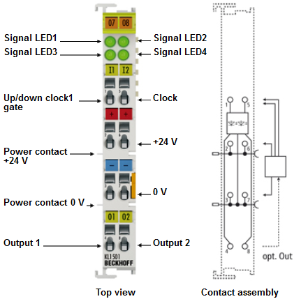
The LEDs indicate the state of the up/down and clock inputs and of outputs 1 and 2.
The representation of the process data differs depending on the set function.
In the standard output format, 5 bytes (4 bytes user data and 1 control/status byte) are mapped. The representation of the process data differs depending on the set function.
- Up/down counter: 32 bit signed integer
- Gated counter: 32 bit unsigned integer
- Two active counters: 2 x 16 bit unsigned integer
If the alternative output format is selected, note that the output length (4 bytes or 6 bytes instead of 5 bytes) and the terminal mapping will change.
- Up/down counter: 24 bit signed integer
- Gated counter: 24 bit signed integer
- Two active counters: 1 x 8 bit counter 0 and 1 x 16 bit counter 1
The terminal mapping is described in more detail in chapter Mapping in the Bus Coupler.