Configuration of axes and channels
Axes
To interrupt machining and to move an axis through another channel, a further logical axis (No. 11), which is linked to an existing physical axis (No. 1) is configured. All data except for the new axis number and the connection can be adopted from the original axis by cloning.
kopf.achs_nr                11
kopf.clone_of                1
kopf.link_to                 1
Channels
The channels are configured with the logical axes in the usual manner.
Channel 1 is assigned the axes 1 to 3 as the main axes
gruppe[0].achs_anzahl               3
gruppe[0].achse[0].log_achs_nr      1
gruppe[0].achse[0].bezeichnung      X
gruppe[0].achse[1].log_achs_nr      2
gruppe[0].achse[1].bezeichnung      Y
gruppe[0].achse[2].log_achs_nr      3
gruppe[0].achse[2].bezeichnung      Z
Channel 2 represents the auxiliary channel and is assigned the axes 11 to 13 as main axes
gruppe[0].achs_anzahl              3
gruppe[0].achse[0].log_achs_nr     11
gruppe[0].achse[0].bezeichnung     X
gruppe[0].achse[1].log_achs_nr     12
gruppe[0].achse[1].bezeichnung     Y
gruppe[0].achse[2].log_achs_nr     13
gruppe[0].achse[2].bezeichnung     Z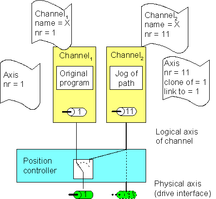
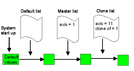
Cloned axis
To generate a cloned axis the source axis must already be existing and initialized before. Cloning an axis just takes the parameters of the first axis the first time. Any later change of axis parameters does not consider the cloned source. It just modifies or overwrites the actual individual axis parameters.
 | The specified clone reference cannot be changed after first initialization. |
Notice | |
Art und Quelle der Gefahr If master axis of clone is not existing an error message is raised and “clone” axis is generated without cloning. |