Temporal aspects of analog/digital or digital/analog conversion
 | Analog output The following information applies analogously to analog signal output via DAC (digital-to-analog converter). |
The conversion of the constant electrical input signal to a value-discrete digital and machine-readable form takes place in the analog Beckhoff EL/KL/EP input modules with ADC (analog-to-digital converter). Although different ADC technologies are used in practice, they have one thing in common from a user perspective: once the conversion process is complete, a specific digital value is available for further processing in the control. This digital value, the so-called analog process data, is to be seen in a fixed temporal relationship with the “original value”, the electrical input value. As a result, corresponding time characteristics can be determined and specified for Beckhoff analog input devices.
Several functional components are involved in the process described, which act to varying degrees in each AI (analog input) module.
- the electrical input circuit
- the analog-digital conversion
- the further digital processing
- the final provision of the process and diagnostic data for collection at the fieldbus (EtherCAT, K-bus, etc.)
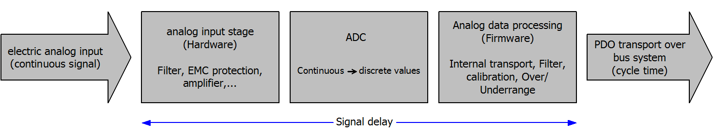 Fig.38: Analog input signal processing
From a user perspective, three aspects are crucial:
- How often are new values received?
This refers to a sampling rate in the sense of the speed of the device/channel. - How much delay does the (entire) AD conversion of the device/channel cause in relation to the individual channel?
Hardware and firmware parts are considered as a whole. For technological reasons, the signal characteristics must be considered when determining this value: depending on the signal frequency, there may be different runtimes through the system. - Is there a time offset in the record between channels?
For devices with simultaneous recording, not by definition: all channels record simultaneously. For multiplexer channels by definition yes, the channels record individually or in groups one after the other. - Further information if applicable
This is the “external” view of the “Beckhoff AI channel” system – internally the signal delay in particular is composed of different components: hardware, amplifier, conversion itself, data transport and processing. Internally a higher sampling rate may be used (e.g. in the DeltaSigma converters) than is offered “externally” from the user perspective. However, this is generally irrelevant from the user perspective of the “Beckhoff AI Channel” component, or is specified if it is relevant to the function.
For Beckhoff AI devices the following specification parameters for the AI channel are available for the user from a temporal perspective:
1. Minimum conversion time [ms, µs]
This is the reciprocal value of the maximum sampling rate [Sps, samples per second]:
specifies how often the analog channel provides a newly detected process data value for collection by the fieldbus. The triggering (start) of the measurement is determined on the device side by the operation mode and can be set, for example, as FreeRun, EtherCAT cycle (“Sync Manager synchronous”) or timer-controlled (DistributedClocks).
Whether the fieldbus (EtherCAT, K-bus) then fetches the process data value/measured value just as quickly (i.e. in common mode), faster (because the AI channel is running in FreeRun) or more slowly (e.g. with oversampling) is then a question of the fieldbus setting and which operation modes the AI device supports.
In EtherCAT devices, the so-called toggle bit in the diagnostic PDO indicates (by toggling) that a newly determined analog value is available.
Accordingly, a maximum conversion time, i.e. a minimum sampling rate supported by the AI device, can be specified.
Corresponds to IEC 61131-2 Chap. 7.10.2 2) “Sampling repetition time”
2. Typical signal delay
Corresponds to IEC 61131-2, Chapter 7.10.2 1) “Sampling duration”. According to this consideration, it includes all device-internal hardware and firmware components, but no “external” delay components from the fieldbus or the control (TwinCAT).
This delay is particularly relevant for absolute time considerations, if AI channels also provide an associated timestamp in addition to the amplitude value, the time value of which can be assumed to correspond to the previously physically present amplitude value.
Due to the frequency-dependent runtime of a signal, a dedicated value can only be specified for a given signal. The value also depends on possibly changing filter settings of the channel.
A typical characterization in the device documentation can be:
2.1 Signal delay (step response)
Keyword settling time:
The square wave signal can be generated externally with a frequency generator (note impedance!).
The 90% limit is used as detection threshold.
The signal delay [ms, µs] is then the time interval between the (ideal) electrical square wave signal and the time when the analog process value has reached the 90% amplitude.
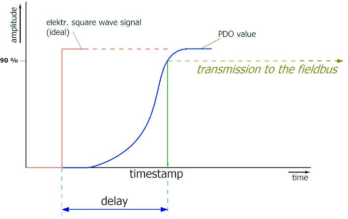 Fig.39: Diagram Signal delay (step response)
2.2 Signal delay (linear)
describes the delay of a signal with a constant frequency
The test signal can be generated externally with a frequency generator, e.g. as sawtooth or sine. Reference would then be a simultaneous square wave signal.
The signal delay [ms, µs] is then the time interval between the applied electrical signal of a certain amplitude and the moment when the analog process value reaches the same value.
For this purpose, the test frequency must be selected in a reasonable range; this can be, for example, 1/20 of the maximum sampling rate.
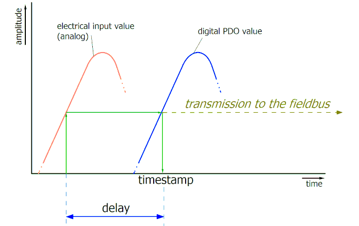 Fig.40: Diagram Signal delay (linear)
3. Time offset between channels/channel groups
If a device multiplexes, the time offset can be specified in the specification. It is generally static, i.e. it does not change.
Note: The measured values of all channels are fetched simultaneously from the bus/EtherCAT! If the multiplexer offset is (significantly) smaller than the cycle time, the time offset in the measured data (e.g. scope recording) is difficult to recognize and, in particular, can hardly be distinguished from amplitude deviations.
A sinusoidal signal with fSine = 45% EtherCAT cycle time has proven to be a good test signal for a rough observation of the effect.
4. Additional information
Additional information may be provided in the specification, e.g.
- actual sampling rate of the ADC (if different from the channel sampling rate)
- Time correction values for runtimes (delay) with different filter settings
- etc.