Shunt calibration
Notes on shunt calibration
Note: Not all Beckhoff strain gauge/bridge measuring devices support shunt calibration.
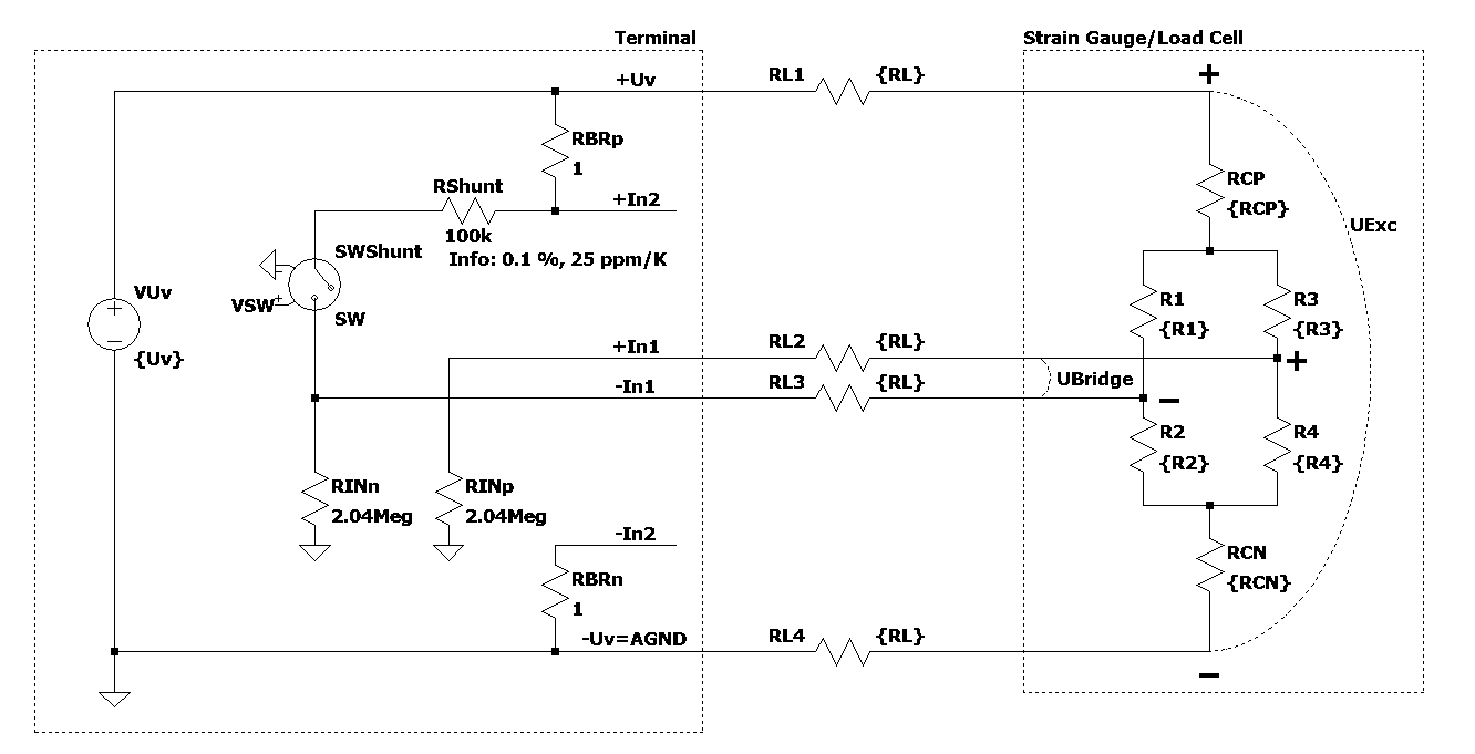
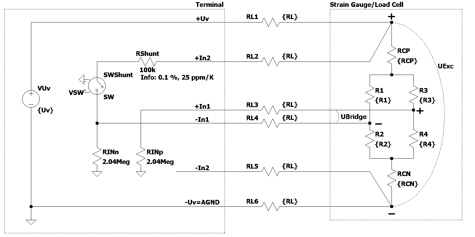
Shunt calibration refers to a procedure in which a known resistor is temporarily connected parallel to a bridge resistor. This is possible with all bridge circuits (quarter/half/full bridge); example for full bridge:
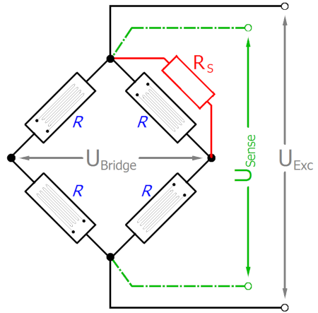
This electrically simulates a load on the measuring bridge; depending on the situation, a measuring signal step change between 0.1 and a few mV/V occurs. The interesting thing is that the step change, which is dependent on all the elements involved, is predictable.
Shunt calibration is used, for example, to
- find wire breakages or wiring faults during commissioning,
- simplify the initial calibration of the measuring setup: if the sensor cannot be loaded, the gain of the electrical measurement can be checked through the known detuning. Data acquisition can be even more extensive if the shunt is installed upstream in the sensor or in the bridge, rather than in the measuring device (in this case the Beckhoff measuring terminal),
- detection of resistance changes (that change the gain) in cables, plugs, full/half/quarter bridge during operation,
- compensate for actual line resistances during commissioning without having to install an (expensive) compensating line. For this purpose, the determined detuning is compared with the theoretically expected detuning and a corresponding gain correction factor is calculated in the PLC or terminal (however, a technically better way with regard to line resistances would be to use compensating lines, i.e. 3-wire mode for quarter bridge, 5-wire mode for half bridge, 6-wire mode for full bridge).
Shunt calibration procedure
- During commissioning, note the measured value at constant load, ideally without load.
- Close the shunt and note the difference to the previous measured value. A signal step change in [mV/V] should occur which corresponds to the precalculated value.
- During system operation the shunt calibration can be repeated regularly. The signal step change should not change significantly; if it does, it is an indication that electrically relevant components may have changed unintentionally.
Theoretically, the expected signal step change is based on the equation:

is 0.875 mV/V for R = 350 Ω and Rs = 100 kΩ.
Formulas and information on shunt calibration can be found in high-quality technical literature (Keil, Hoffmann) and can in some cases be obtained from bridge manufacturers (Vishay, HBM). However, it should be noted that the actual bridge design in commercially available measuring bridges/strain gauges often goes beyond the fundamentals described in simple standard works with R1...R4 = R. It is important to be aware of this, in order to be able to predict the signal step change [mV/V] during shunt calibration. Therefore, some aspects of actual measuring bridges are described below. Please note that the information is provided for general guidance only; for actual applications the user should discuss the finer details with the bridge manufacturer.
Input vs output impedance
Professionally manufactured measuring bridges/full bridges consist not only of the four bridge resistors R1, R2, R3, R4, but include a number of additional resistors and other sophisticated components, e.g. to compensate for temperature and non-linearity effects. The nominal or rated resistance of 120 or 350 Ω always refers to the output impedance (output resistance) of a bridge, i.e. the resistance that the measuring device sees at UBridge.
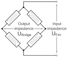
Theoretically the input impedance (input resistance) is the same, although in practice it is up to 25% larger than the output impedance, since, for example, with 350 Ω bridges, 2x approx. 32 Ω are often installed (for background on this see e.g. Stefan Keil, “Beanspruchungsermittlung mit Dehnmessstreifen”, 1995, Chap. 5.3), which are also detected by the sensor:
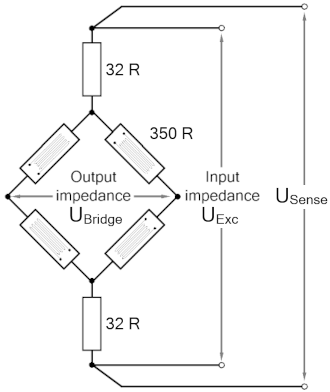
This is irrelevant in non-shunt mode, in which the load on the supply is actually reduced. However, in shunt mode this information is crucial if the signal step change is to be predicted correctly. In addition, bridge designs vary greatly across the world, depending on the manufacturer and price range; in some cases bridges are asymmetrical in terms of UExc.
Line resistances
The shunt bridges supply lines, which means the influence of their resistance must also be known or measured in order to be able to predict the signal step change. Formulas and information on resistances of cables, connectors and switches can be found in the specialist literature, manufacturer data sheets and internet sources. Values in the range of a few 10s to 100 mΩ are common for short lengths.
Step change prediction
Due to the different characteristics of bridges and environments, no comprehensive values or formulas for step change prediction in [mV/V] can be provided here. More meaningful is specific calculation according to the respective conditions, taking into account the components that are essential for the shunt calibration. Common simulation tools are available for this purpose; further information can be requested via measurement@beckhoff.com.