Measurement of Strain Gauge Resistance Changes
The change in resistance of an individual strain gauge can be determined in principle by resistance measurement (current/voltage measurement) using a 2/3/4‑wire measurement technique.
Usually 1/2/4 strain gauges are arranged in a Wheatstone bridge (‑> quarter/half/full bridge); the nominal resistance/impedance R0 of all strain gauges (and the auxiliary resistors used if necessary) is usually equivalent to R1 = R2 = R3 = R4 = R0. Typical values in the non‑loaded state so are R0 = 120 Ω, 350 Ω, 700 Ω or 1 kΩ.
The full bridge possesses the best characteristics such as increased linearity in the feeding of current/voltage, up to four times the sensitivity of the quarter‑bridge as well as systematic compensation of disturbing influences such as temperature drift and creeping. In order to achieve high sensitivity, the four individual strain gauges are arranged on the object to be measured (the carrier) in such a way, that two are elongated and two are compressed in each case.
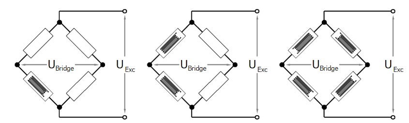
At this point, the three most important voltages in the bridge environment are defined:
- UExc:
- this is the feed voltage of the bridge as it comes from the measuring device or from an external source,
- usually in the range 1…12 V DC,
- it is fed to the bridge via supply line. Since current flows there, a voltage drop always occurs across the supply line; therefore, the bridge effectively only sees a voltage < UExc,
- other terms: UV, US, excitation, supply.
- USense:
- this is the bridge supply voltage as the measuring device “sees” it,
- usually in the range 1…12 V DC,
- without an extra sense supply line (e.g. 6‑wire operation of the full bridge) it is equal to UExc in the measuring device,
- if the bridge is operated with a sense line (full bridge: 6‑wire operation, half bridge: 5‑wire operation, quarter‑bridge: 3/4‑wire operation), USense returns to the measuring device from the bridge virtually current‑free and the measuring device knows the "true" UExc of the bridge,
- other terms: URef, reference, RemoteSense, feedback, compensation.
- UBridge:
- this is the very small differential bridge voltage "generated" by the load in the bridge, which is to be measured by the measuring device,
- it returns to the measuring device from the bridge virtually current‑free and is mostly in the range 1..50 mV, depending on the magnitude of UExc, the load and the bridge sensitivity,
- other terms: UD, UDifferential, signal, AI.
The measuring bridges can be operated with constant current, constant voltage, or also with AC voltage using the carrier frequency method.
 | Measuring procedure The Beckhoff EL/KL335x terminals and the product group measurement technology ELM35/37xx, EPP35xx only support excitation with constant voltage. If excitation with AC is required, please contact Beckhoff sales. |
Full bridge strain gauge at constant voltage (ratiometric measurement)
Since the relative resistance change ΔR/R is low in relation to the nominal resistance R0, a simplified equation is given for the strain gauge in the Wheatstone bridge arrangement:
U D /U V = ¼ · (ΔR1‑ΔR2+ΔR3‑ΔR4)/R 0 .
ΔR/R usually has a positive sign in the case of elongation and a minus sign in the case of compression.
A suitable measuring instrument measures the bridge supply voltage UExc (or UV) and the resulting bridge voltage UBridge (or UD), and forms the quotients from both voltages, i.e. the ratio. After further calculation and scaling the measured value is output, e.g. in form of the effective mass in kg. Due to the division of UBridge and UExc the measurement is in principle independent of changes in the supply voltage.
If the voltages UBridge and UExc are measured simultaneously, i.e. at the same moment, and placed in relation to each other, this is referred to as a ratiometric measurement.
The advantage of this is that (with simultaneous measurement!) brief changes in the supply voltage (e.g. EMC effects) or a generally inaccurate or temporal unstable supply voltage likewise have no effect on the measurement.
A change in UV by e.g. 1 % creates the same percentage change in UD according to the above equation. Due to the simultaneous measurement of UD and UV the error cancels itself out completely during the division.