Bandwidth, sampling rate and impedance of the measurement inputs
Microphones and IEPE sensors (structure-borne sound, accelerations) are highly dynamic sensors that require a measurement input with a sufficiently high bandwidth and high sampling rate. To be able to detect a frequency of up to 10 kHz, a sampling rate of more than twice the signal frequency, but preferably five times the signal frequency, is required. The measuring device must therefore have a bandwidth of significantly more than 10 kHz and sample with at least 20 ksps.
Usually, the usable bandwidth is specified at an attenuation of -3 dB (which already represents a significant amplitude reduction, see chapter Notes on analog aspects ‑ dynamic signals). Therefore, a measuring device with a bandwidth greater than 10 kHz should be used.
Significantly better amplitude detection is only possible with a higher sampling rate of fSampling ≥ 5 fSignal, which should also be used if possible.
For dynamic signals in the kHz range, the input impedance of the measuring device (combination of resistance and capacitance) can play an important role, depending on the signal source. A high input resistance and a low input capacitance are optimal for a low load on the source signal.
Notice | |
Device documentation is solely authoritative The values may be shortened extracts from the respective documentation, which is decisive and recommended for detailed analysis. |
Some measurement terminals with indication of the RC parallel circuit on the input side:
Terminal | Measuring ranges | Differential input resistance | Differential input capacitance |
|---|---|---|---|
ELM3002-02x5/-4x5 | ≥±60 V | 10 MΩ | < 1 nF |
ELM3002-03x5/-4x5 | <±60 V | 20 MΩ | < 1 nF |
ELM3102-0100 | ±60 V | 485 kΩ | < 11 nF |
ELM3102-0100 | <±60 V | 4.12 MΩ | < 11 nF |
Exemplary calculation:
The impedance of the RC parallel circuit can be calculated with

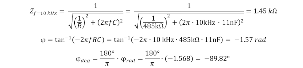
The phase angle φ is calculated with
φ = tan-1( -2π ƒ R C )
For f = 10 kHz and an ELM3002-0305 in the 150 mV measuring range (with 20 MΩ || << 1 nF parasitic capacitance, see technical data), this results in an impedance of
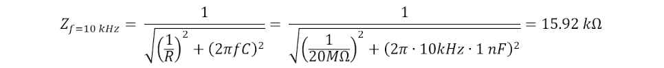
As well as a phase angle φ of

The input therefore behaves capacitively, the current leads.
If the same boundary conditions are applied to an ELM3102-0100 for the 60 V measuring range, the values change to
This means that the ELM3102-0100 (measuring range 60 V) loads the source, e.g. a microphone, with an impedance that is approx. 10 times lower than that of the ELM3002-0305. Assuming a source with 100 Ω internal resistance, the systematic amplitude error for f = 10 kHz is:

However, the measuring bandwidth of these measuring devices differs significantly: While the ELM3102-0100 has a bandwidth of f = 5.3 kHz (-3 dB) and can therefore no longer sensibly detect the input signal required in the example, the ELM3002-0305 has a bandwidth of f = 21.7 kHz (-3 dB) and is better suited for higher frequency signals while at the same time requiring precise measurement.
Measurements with differential voltages > 5 V and high-resistance sources
The internal resistance of the source forms a frequency-dependent voltage divider with the impedance of the measurement input. While the input resistance from the specification is used for DC voltage, the impedance must first be calculated for dynamic signals. This is then used in the calculation of the voltage divider.
For a direct comparison of both terminals, a signal frequency of 4 kHz in combination with a high-resistance source with RSource = 1 kΩ is well suited. The following terminals are chosen for a voltage of ±30 V to be measured:
- ELM3002-0205 in the ±60 V measuring range (R = 10 MΩ, C = 1 nF)
- ELM3102-0100 in the ±60 V measuring range (R = 485 kΩ, C = 11 nF)
The following apply in this configuration, dominated by the respective capacitances C:
ZELM3002-0205 = 39.8 kΩ
ZELM3102-0100 = 3.62 kΩ
This results in a systematic amplitude error of:

Conclusion: A low input capacitance is particularly important when dynamic signals are to be recorded with high-resistance sources in order to achieve the smallest possible amplitude error.