Measurement of differential signals with high common-mode offset
There are sensors that require an offset voltage to supply the sensor-internal electronics, which supplies the internal electronics and can provide a differential output signal.
Examples:
- Microphones with 48 V phantom power
- IEPE sensors (constant current supply in the mA range)
- Hall sensors
This output signal contains the dynamic signal information of the physical input variable in frequency and amplitude, which the sensor translates with its sensitivity into an electrically measurable signal.
48 V phantom power
Phantom power is a special form of power supply. Applied to the microphone, it enables the output of a differential output signal or a differential measurement as well as two single-ended signals with ground reference:
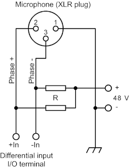 Fig.68: 48 V phantom power circuit for microphones
The resistors R are used to decouple the phase+/phase- lines so that no short circuit occurs between the two lines. The output signal is connected to a differential measurement input designed for voltage measurement in the mV range.
Example: Two differential signals supplied by the microphone with an amplitude of ±40 mV (peak-peak: ±80 mV), a frequency of 500 Hz and an offset voltage (phantom voltage) of 48 V are measured as individual phase+/phase- signals:
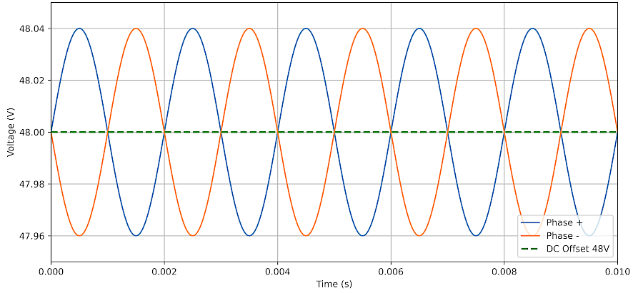 Fig.69: Differential signal with 48 V phantom power, 500 Hz
If the phase+ and phase- signals are used at a differential input, the difference between the two signals is present and is recorded as an analog signal with an amplitude of 80 mV (peak-peak: 160 mV). Note the reduction in the voltage level:
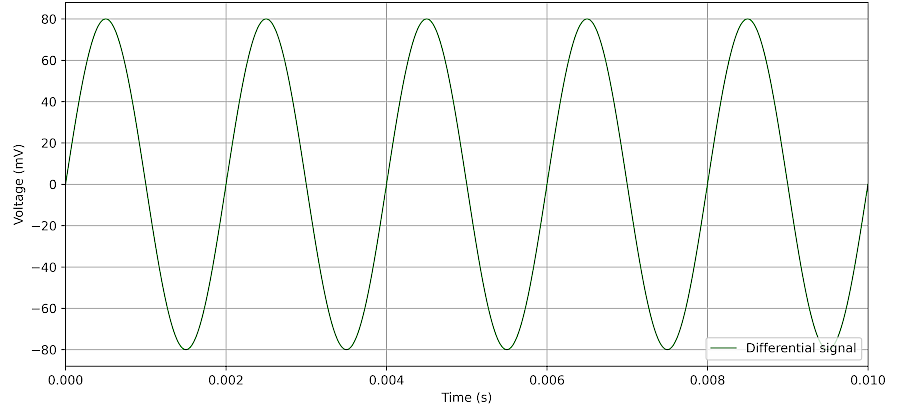 Fig.70: Differential signal without 48 V phantom power, 500 Hz
The voltage of 48 V to ground should not be considered in this differential measurement, as it is a common-mode voltage that is present on both input contacts. However, it should be noted that the measuring device should have electrical isolation between the measurement input and ground (SGND, DIN rail or housing for ELM3xxx). Electrical isolation between measuring channels is also recommended so that each channel has its own internal analog GND (AGND) and the AGNDs cannot influence each other via several channels. For measurement inputs with common AGND in combination with input signals, the 48 V phantom power can lead to impermissibly high potential shifts that can permanently damage the measurement inputs.
Examples of terminals with electrically isolated channels (as of 2026-01):
- ELM3002-02x5/-3x5/-4x5: high-voltage measurement terminals, isolated
- ELM3102-0100: measurement terminal with U/I input, isolated
- ELM3702-0101: multi-function measurement terminal, isolated
Notice | |
Device documentation is solely authoritative The values may be shortened extracts from the respective documentation, which is decisive and recommended for detailed analysis. |
Comparison of the potential groups
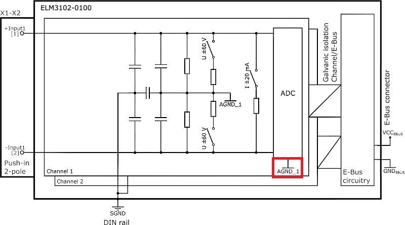
When comparing the potential groups, it becomes clear that the measurement inputs of isolated terminals are completely isolated in contrast to measurement terminals with common AGND potentials:
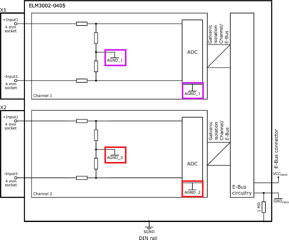
The ELM3102-0100 only has a capacitive coupling to the SGND, the AGND potentials are separate:
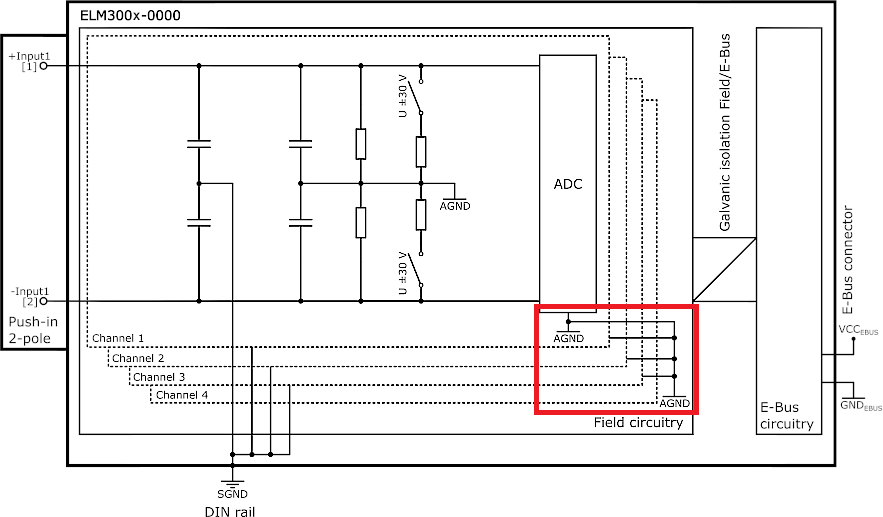
With ELM300x-0000 and other terminals, there is a coupling via a common AGND and a capacitive coupling to SGND:
IEPE sensors and common AGND potentials
With IEPE sensors, a constant current supply is used in which the sensor adjusts to the bias voltage specified in the sensor data sheet on the output side after the transient process without external dynamic acceleration (a = 0). This is usually in the range of 8 … 12 V. The dynamic voltage change at the sensor output, which the sensor generates due to the acceleration acting on it and its sensor sensitivity, is ±5 … 10 V, depending on the sensor. This results in a total voltage level of approx. 0 … 20 V. From the point of view of the AGND potentials in the associated measurement terminals such as ELM360x-000x, no electrical isolation is required between the channels, as no potential shifts > 20 V can be caused by the supply from the terminal.