Readjusting the specification
The analog input terminal is a function block of the modular DIN rail-mountable IP20 system. It follows that there is an almost infinite number of combination options for terminals on the DIN rail, size of the terminal segment, and also a wide range of applications at different ambient temperatures, control cabinet configurations or packing densities. Other influencing factors affecting an analog input terminal as measuring device include cable routing, EMC and earthing measures, the ventilation situation and contamination. In order to ensure reliable replication of the assured specification, despite this variety of factors, a reference configuration is defined below, which should be used as reference environment for verifying the properties of one or several terminals.
NOTE: This does NOT mean that the terminal specification can only be met with this exact configuration. The reference configuration should only be used as an aid for creating a uniform environment for Beckhoff and customer hardware, in order to ensure comparability of the measurement results and simplify the analog communication. This configuration enables undesirable interference in the real system to be separated from the terminal, to facilitate troubleshooting of the system.
The configuration is within the definition space of IEC 61131-2 and essentially follows the rules of EMC-compliant control cabinet construction.
Definition of the environment
- The terminals to be examined should be self-cooling through unobstructed natural convection. All further details are based on this premise
- The terminals are installed in an enclosed control cabinet. This control cabinet is located in a temperature-controlled environment, e.g. a temperature chamber. The control cabinet should have the following dimensions: 600 mm x 600 mm x 350 mm (width x depth x height). The lid must open to the front.
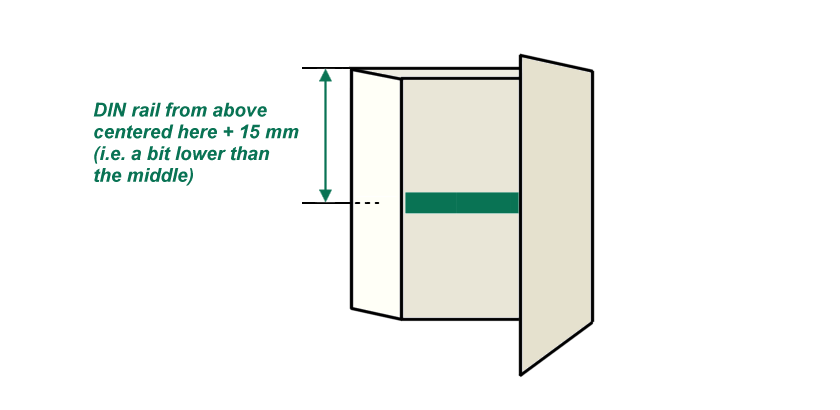 Fig.54: Representation the mounting position of the DIN rail
- A 35 mm x 15 mm DIN rail according to EN 50022 is used for the mounting. This rail is mounted horizontally at the rear panel of the control cabinet. It must extend over the entire width of the control cabinet. The DIN rail must be installed such that the terminals are positioned vertically and exactly centrally in the control cabinet. The terminals should also be centered horizontally.
- The DIN rail must conductively connected to the control cabinet. The DIN rail is earthed with a cable (low-interference PE). Ensure the door is properly connected.
- The supply lines to the devices under test and the power feed terminals should exit at the front. The space above and below the terminals must be clear. The supply lines should be bundled such that convection in the control cabinet is obstructed as little as possible.
- The control cabinet temperature is measured according to IEC 61131-2 at the indicated position at the air inlet point upstream of the terminal when the unit is ventilated. The ambient temperature must be measured with a (verifiable) accuracy of better than ±0.2 °C. The temperature sensor must be mounted horizontally. The temperature outside the control cabinet must be controlled such that the temperature at the measuring point is a constant 23°C.
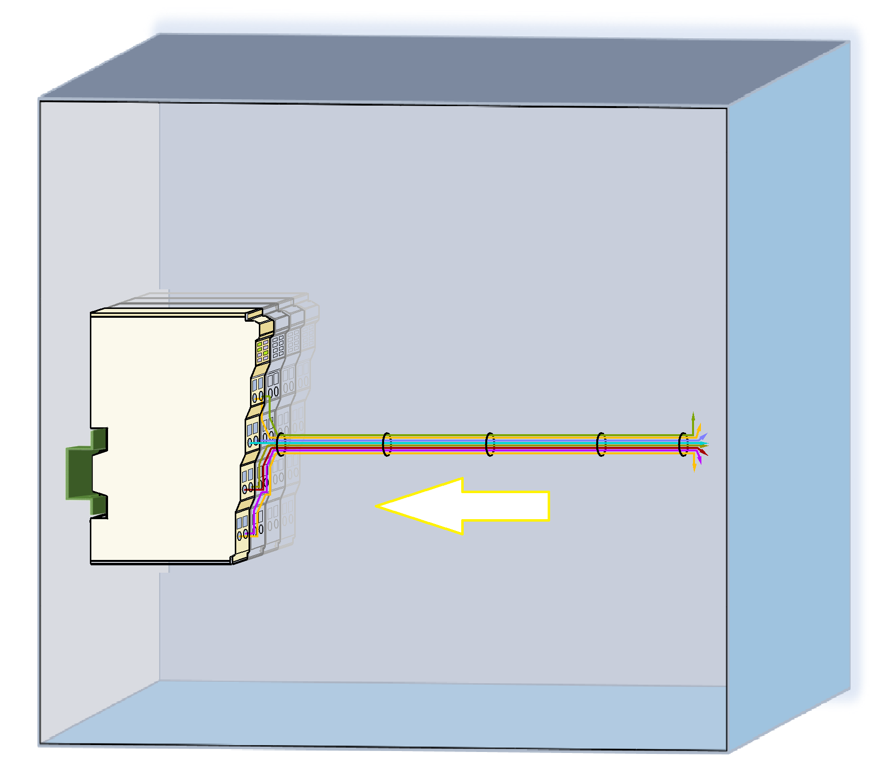 Fig.55: Arrangement of the supply lines to and from the device under test in the control cabinet
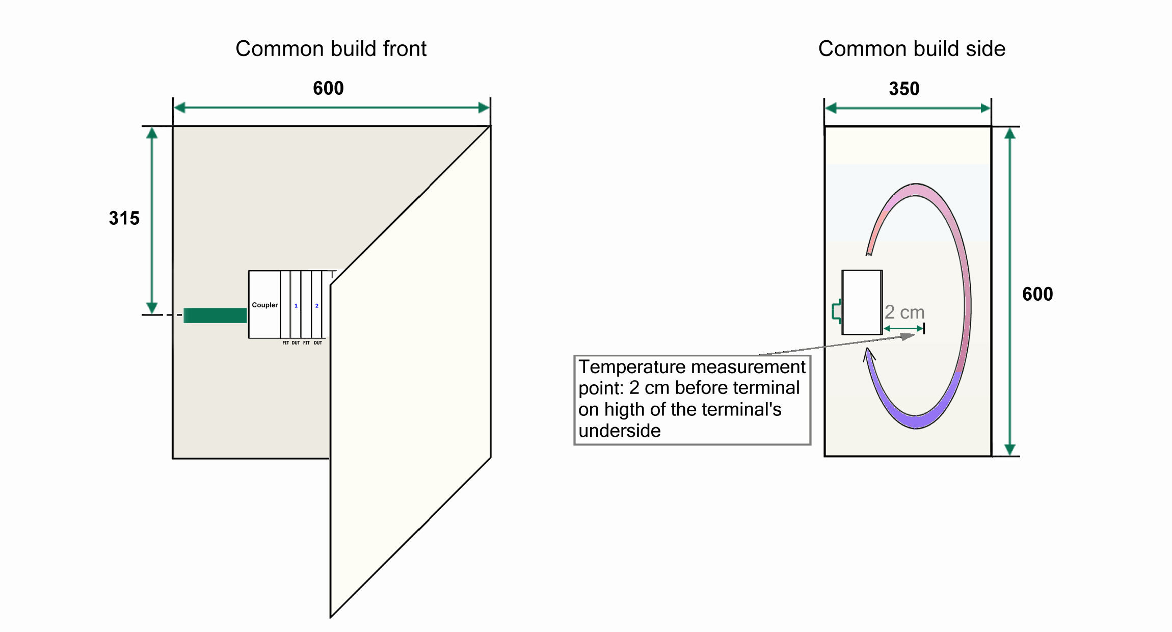 Fig.56: Dimensions and installation in the control cabinet
- The control cabinet must be empty, except the terminals that are part of the measurement configuration, the supply lines and the temperature sensor.
- Any other terminals that may be required must be installed outside the control cabinet. The control cabinet feed-through should match the supply lines.
- Shielded cables should be used for the signal lines. The shield should be connected to the DIN rail. State of the art shielding should be used; cf. widely available documents, e.g. from ZVEI. Components from the Beckhoff shielding connection system (ZB8500, ZB8510, ZB8520) should be used for this purpose. The shielding should be connected on one side to the devices under test and the control cabinet.
Definition of the configuration
- The following terminals are required for the measurement configuration as a minimum; the configuration can include 2-10 devices under test. Configuration as follows, based on two devices under test as an example:
- 1x Bus Coupler EK1100
- 2x terminals to be measured ("devices under test")
- 4x EBUS/KBUS power feed terminal EL9410
- 1x bus end cap/end terminal EL9011
- The terminals are then lined up as shown below (for 2 devices under test):
- For thermal reasons, 2x EL9410 are connected at the end of the terminal segment. These ensure that the preceding "devices under test" 2 is operated in a way that is thermally similar to a center position in the terminal segment.
- Both supply voltages (Us and Up) must be connected to the Bus Coupler and all power feed terminals. The operating voltage must be +24 V ±0.5 V, unless an individual terminal requires a different Up voltage.
- The ground connections of Us and Up may be short-circuited. The PE connections of the Bus Coupler and the power feed terminals do not have to be connected.
- If the devices under test have shielding (functional earth) at a terminal point, this must not be connected, since the terminals have a shield spring on the DIN rail at the rear.
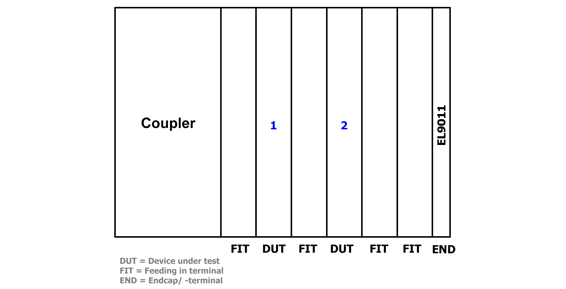 Fig.57: Schematic diagram of the test configuration