Connection techniques and supply line resistance compensation
Inevitably, when using RTD sensors, they can only be measured via supply lines. The supply lines to the sensor each have a (temperature-dependent!) internal resistance, which influences and falsifies the measurement. In addition, insulation faults or thermovoltages, for example due to uneven temperature distributions, can also influence the measurement. These must be checked by the user and taken into account depending on the application. In addition, RTD sensors react to the self-heating that occurs, so that this also influences the measurement result. Various connection techniques and special sensor data help to compensate for the supply line resistances, and the sensor self-heating can also be calculated with the aid of special sensor data. Possible connection techniques are two-wire, three-wire and four-wire. The individual advantages and disadvantages of the respective connection technology are attached to the explanation of the connection technologies. Direct resistance measurement with reference resistor is assumed.
- Two-wire technique
- The sensor is connected without additional wires.
- This connection technology requires little connection material and is used for simple RTD temperature measurements
- Recommended for short supply lines or simple measurements only
- Transition resistance values of the terminal contacts affect the measurement. An adjustment by the user with the signal connection plugged in can increase the measuring accuracy again, but must be repeated regularly.
- For the compensation of the supply line resistances, the fixed supply line resistance can be determined by a measurement or an adjustment and then subtracted from the measurement result, another connection technique can be selected or a sensor with a high nominal resistance can be selected
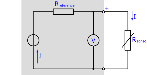 Fig.11: Connection RTD sensor two-wire technique
Example of supply line compensation with the two-wire technique
Given is a 50 m long supply line made of copper with a line cross-section of 0.5 mm2. The resistivity of copper is equal to 0.0175 Ω mm2 m-1 at room temperature.
Determination of the total resistance of the supply line:
RLtot= 0.0175 Ω mm2 m-1 ⋅ (2 ⋅ 50 m / 0.5 mm2) = 3.5 Ω
A Pt100 sensor has an average resistance change of ≈ 0.39 Ω/K. With a line resistance of RLtot = 3.5 Ω, this results in a static temperature deviation of 3.5 Ω / (0.39 Ω/°C) = 8.97 °C if this is not taken into account. The calculated 3.5 Ω can be subtracted from the measured value after the measurement (before the R → T transformation), so that the supply line resistances do not influence the measurement result (at least at this moment).
A change in the resistivity of the supply lines due to aging or temperature change will not be noticed in this case! For an exact calculation of the supply line resistances, these factors must be taken into account. For example, the temperature dependence of copper lines is not insignificant at ~4000 ppm/K (0.4%/K) in 24/7 operation.
- Three-wire technique
- The sensor is connected with an additional wire, so that another measuring circuit is created.
- This measuring circuit is used to determine the resistance of the supply lines excluding the connected sensor, so that the supply line resistance can be determined directly and subtracted from the measured value
- Line "+" and "-" must have the same electrical properties here
- This connection technology theoretically offers more accurate temperature measurement at only slightly higher installation costs.
- Due to the cost reduction compared to the four-wire technique and a nevertheless more accurate measurement result compared to the two-wire technique, the three-wire technique is the most common industrial connection technology for resistance sensors.
- Transition resistances of the terminal contacts influence the measuring process (an adjustment by the user with the signal connection plugged in can increase the measuring accuracy again)
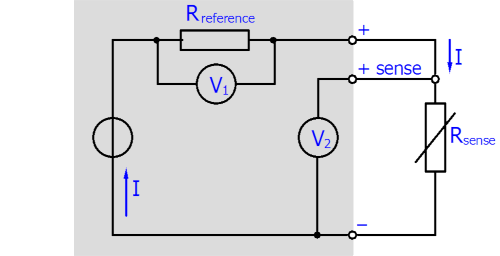 Fig.12: Connection RTD sensor three-wire technique
- Four-wire technique
- The sensor is equipped with two additional sense lines so that the current conduction and voltage measurement run over separate wires.
- The wires for currentless voltage measurement are thus not subject to voltage drop.
- This connection technique is recommended within the scope of exact temperature measurements, since the output measured value is line neutral.
- Especially for resistance measurements of very small resistances (range about < 10 Ω) the use of the four-wire technique is required (also to be considered is the relative measurement deviation with respect to the FSV - the use of measuring terminals with smaller resistance measuring ranges is recommended).
- With the help of the four-wire technique, the influence of the supply lines can be completely and permanently compensated.
- A high level of cabling is required for four-wire technique.
- However, the adverse effect of thermovoltages may still occur.
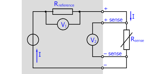 Fig.13: Connection RTD sensor four-wire technique