Structure of resistance sensors
Two different common designs of RTD sensors exist, each having its advantages and disadvantages. As a rule, RTD sensors are inserted in a protective and non-conductive housing, depending on the application, so that external influences cannot affect the measurement result and a stable sensor design is ensured.
- Thin-film RTD sensors
A thin layer of the temperature-sensitive material (e.g. platinum) is applied to a non-conductive substrate (often ceramic). The length of the temperature-sensitive layer sets the nominal resistance of the sensor. The measurement layer is then sealed to protect it from external influences (usually with a layer of glass or epoxy resin).
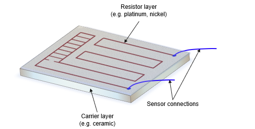 Fig.6: Thin-film RTD sensor
Thin-film sensors are cost-effective due to their simple design, which requires less temperature-sensitive material, and can be manufactured in more customized shapes. However, the resistance value R0 at T=0 °C cannot be set as accurately as wired RTD sensors, so thin-film sensors generally have greater uncertainty. In addition, due to their small size, they are more affected by self-heating of the sensor and therefore tend to be used at low temperatures.
- Wired RTD Sensors:
A measuring wire, consisting of the temperature-sensitive material, is shortened according to the desired nominal resistance and then wound. The measuring wire is wound around or embedded/melted into a non-conductive rod as a core and enclosed by a non-conductive tube. Depending on the application, glass, ceramics, etc. are used as the non-conductive material. The most common design is shown in the figure below:
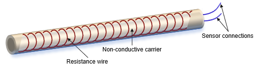 Fig.7: Wired RTD sensor with measuring wire