Note on oscillation effects with analog 20 mA inputs
The standard analog signal "20m" (0...20 mA, 4...20 mA) is used for simple information transport between a signal transducer (usually a sensor) and the measuring device (here: Beckhoff analog input in the form of an IP20 terminal, IP67 box or similar).
For this purpose, it is important that the encoder/sensor can drive the set current I0 (here: 20 mA) through the measuring device. Accordingly, the voltage Usensor available at the sensor must be high enough to drive the set current through the "load" in the measuring device Rmeasuring device; this results in the load impedance from:
Rmax, measuring device = Usensor / I0.
As a rule, the sensor manufacturer specifies the max. permissible load impedance Rmeasuring device in its data sheet. Similarly, for most 20 mA measuring devices, the load impedance should be specified in the associated data sheet; for some Beckhoff EL3xxx Terminals, for example, it is 85 Ω.
In detail, however, the sensor (signal source) and the measuring device (signal sink) also form a complex network of various impedances, since both sides (must) contain capacitive/inductive elements for EMC protection reasons. In spite of the fact that both sides are designed in accordance with the specifications, however, an unfavorable combination of these impedances within the circuit consisting of the sensor and the measuring device can lead to permanent oscillations, which are superimposed on the signal to be measured from the sensor and thus falsify it: it must be taken into account that the capacitive/inductive elements, together with the regulation of the sensor voltage, cause the circuit to oscillate (the sensor may try to apply its set current "very dynamically").
Real observed examples of this with different combinations:
- Oscillation of about 200 kHz with amplitude ±3.6 V around an offset of about 0.2 V at the 85 Ω load of the input terminal used here; the analog input apparently measures about 2.3 mA.
- Oscillation of approx. 100 kHz with amplitude ±0.2 V around approx. 1 V, measured at the load of an input terminal
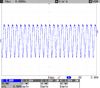 Fig.58: Oscillation signal at load of an analog input terminal in the 20 mA measuring range (X: 10 µs/div, Y: 2 V/ div)
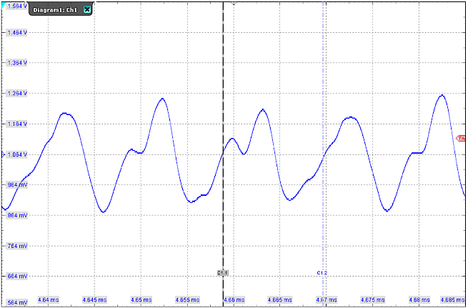 Fig.59: Oscillation signal at load of an analog input terminal in the 20 mA measuring range (X: 5 µs/div, Y: 100 mV/ div)
Depending on how fast the measuring device scans, it then detects a more or less incorrect measured value, which may not change even if the sensor signal changes. Since this involves oscillations in the kHz range, the oscillating, distorted sensor signal can only be recorded from the control point of view by a measuring device (e.g. oscilloscope) with a high sampling rate (>>1 kSps).
In case of obviously wrong measurement, check first:
- Correct sensor connection, sensor supply, wiring,
- Transition resistances, wire breakage, connector, shielding, interferences
- Compatibility of the load (see above)
If permanent oscillation is still suspected after this,
- the effect on the 20 mA line can be determined by oscilloscope (see above),
- a series resistance of several 10 Ω (e.g. 100 Ω) can be inserted into the 20 mA line as a test; the system is thus changed and the tendency to oscillate is usually reduced.
To remedy this,
- you can use a functionally identical input of another series: e.g. EL307x instead of EL301x/ EL302x/ EL304x/ EL305x; EL317x instead of EL311x/ EL312x/ EL314x/ EL315x or,
- the experimentally determined series resistance can be used permanently (observe max. permissible load!).