Tool radius compensation
In the case of classical free-form area machining, tool geometry compensation is already realized in the CAD/CAM system.
The following must be considered when using tool radius compensation during 2.5D machining or when machining inclined surfaces.
Tool radius compensation generates contour elements that are offset, starting from the original contour, by the tool radius. Based on these interpolation points or the contour elements, polynomials are calculated online, i.e. in the CNC. The result, however, is dependent on the interpolation point density, the chosen interpolation method, and the nature of the contour description via linear and/or circular blocks. Two typical examples in combination with the Akima spline are shown below. When the B-spline is used, a greater error must be expected because the spline uses the interpolation points calculated by tool radius compensation as check points only.
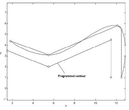 Fig.26: Akima spline interpolation with active tool radius compensation
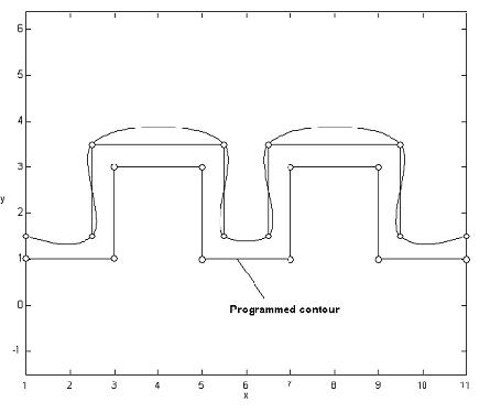 Fig.27: Akima spline interpolation with active tool radius compensation
When the spline function is active and G02, G03 blocks are programmed, spline generation is interrupted and a tangential transition into the circular block is generated. When tool radius compensation is used in a pure linear block program, this can insert transition circles depending on the operating mode.