Contour interpolation points
An adequately high contouring speed can only be achieved if the interpolation point profile of the NC program generated is a harmonious one. This influence becomes all the stronger the shorter the motion blocks are. By way of example, Figure 1-22 shows the scanned linear interpolation points for an axis. Therefore, each interpolation point represents an NC block. Due to the relatively extreme fluctuations of the relative travel distances in relation to path travel (Figure 1-23), the resulting speed profile for this axis fluctuates considerably. This also has a negative impact on machining accuracy. This interpolation point variant can generally only be interpolated by means of a highly smoothing process such as the B-spline process. It is better, however, to use a suitable filter function in the CAD/CAM system because only this system possesses information about the original contour.
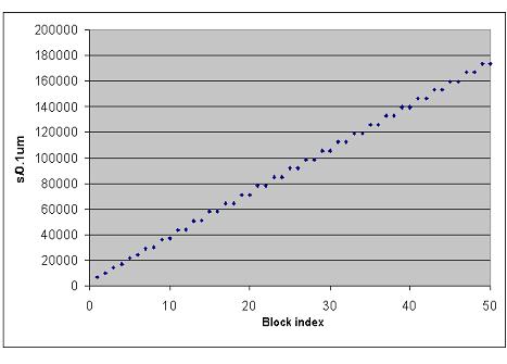 Fig.22: Axis positions scanned by a CAD/CAM system
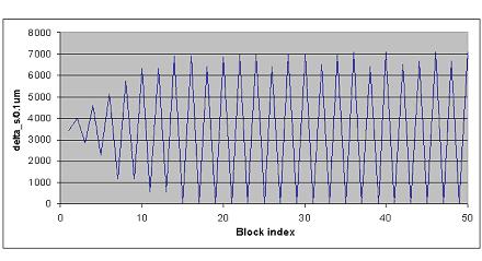 Fig.23: Block-related relative travel distance of the axis
In the case of five-axis machining, a harmonious interpolation point profile is particularly important because, in certain circumstances, tool compensating motions have to be generated by the CNC here.
The axis positions and the block-related relative travel distance after smoothing via a simple averaging filter (e.g. in the CAD/CAM system) are shown here.
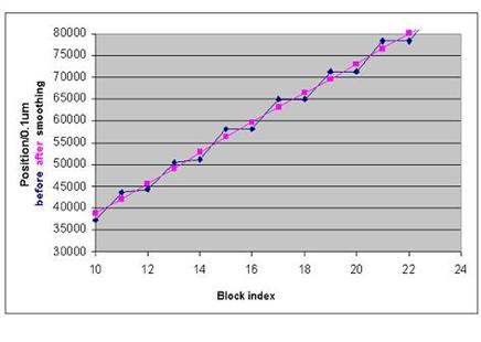 Fig.24: Scanned positions of the axis
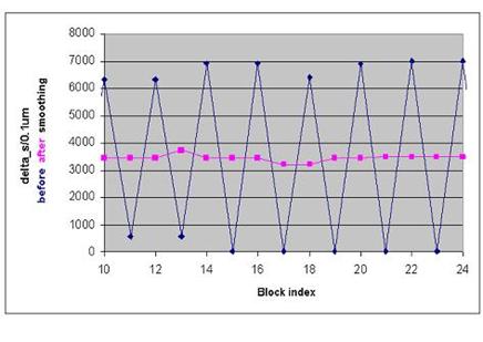 Fig.25: Block-related relative travel distance of the axis