Description
Principle
The following error is caused by the control system's velocity, acceleration and jolt delay in the position controller with respect to the calculated command variable in the interpolator. In the interpolator, the feedforward control calculates the theoretical following error tat would result from the current velocity and acceleration in the position controller and, on the basis of this, it determines a velocity setpoint vfeedforward that is added to the position controller's output (Figure 1-1). This additional setpoint can be weighted with a factor.
The expected following errors can be calculated in accordance with the relationship

for constant velocity

and for constant jerk

for constant acceleration. Ta is the mechanical time constant of the drive, Kv the psosition controller gain.
Alternatively, the command velocities and accelerations calculated in the CNC control can be transmitted as additve command velocity and torque values to the drive controller and fed into the appropriate control loops as additive command values (see picture 1.2).
Feedforward control modes
Based on the cause of the following error, the control system distinguishes between the following feedforward control modes:
- Velocity feedforward control and
- Acceleration feedforward control.
- Jerk feedforward control.
Both feedforward control modes can be activated or parameterized independently of one another.
Activation
The P-AXIS-00223 parameter activates feedforward control for each axis or spindle. When the corresponding bits are set, the feedforward modes are selected, and further control information is also activated. The feedforward control mode is selected in the NC program.
Weighting
Feedforward control can be weighted with two axis-specific weighting factors. The entire feedforward control is weighted with the P-AXIS-00228 and P-AXIS-00229 parameters.

Acceleration feedforward control can also be weighted with the substitute time constant Ta, which is determined on the basis of the P-AXIS-00225 and P-AXIS-00226 parameters.

Jerk feedforward control can also be weighted with a factor

which is determined with parameters P-AXIS-00337 and P-AXIS-00338.
 | According to experience, the entire feedforward control can be weighted with a factor within the range of 0.71. At values more than 1, the axis leads and has a detrimental influence on contouring accuracy. |
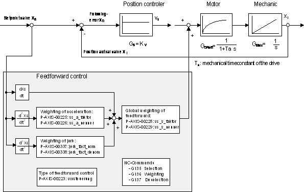 Fig.1: Block diagram of conventional feedforward control
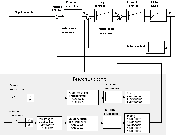 Fig.2: Block diagram of feedforward control with additive command values
 Parameterization for PROFIdrive
In the case of PROFIdrive, the control system currently only supports the telegram 5. PROFIdrive also requires the parameters
- P-AXIS-00092: position sensor increments per motor revolution and
- P-AXIS-00165: time offset of feedforward control setpoints,
which must be set in the axis parameter lists.
In the case of PROFIdrive, with the P-AXIS-00223 parameter it is also possible to select how the calculated feedforward control value is passed on to the drive:
- P-AXIS-00223, bit 9 = 0: The feedforward control value is calculated into the control deviation (XERR signal No. 25) as a following error.
- P-AXIS-00223, bit 9 = 1: the feedforward control value is included in calculations as the velocity in the velocity setpoint (NSOLL_B signal No. 7).
Notice | |
SERCOS drives If, in the case of SERCOS drives, feedforward control is not to be realized in the drive, but in the NC control system, the Kv factor in the axis parameter list must be set equal to the Kv factor of the SERCOS drive (S-0-0104).Note: In the case of SERCOS drives, feedforward control is realized in the drive itself and is set with the following parameters:IDN: S-0-0296: Velocity feedforward gainIDN: S-0-0348: Acceleration feedforward gain |
Programming
Feedforward control is programmed in the NC program with the modally active commands G135, G136 and G137 [PROG].
Selection of feedforward control
Feedforward control is explicitly deactivated every time the program is started. Axis group-specific activation of feedforward control is programmed with the NC command G135.
Feedforward control weighting
An axis-specific percentage weighting is assigned to the calculated feedforward control quantities via G136. It is limited for all axes to 100%. The weighting factors are reset to 100% after every program start. If feedforward control is activated or deactivated during the NC program, the weighting factors remain set to the values set by G136. For axes for which no G136 has been programmed, the weighting factor remains set to 100%.
It is also possible to enter selection and weighting of feedforward control in a block.
Cancellation of feedforward control
G137 is used to deactivate feedforward control a specific axis group.
Deactivating individual axes
In the case of axes for which no feedforward control is to be implemented after global selection with G135, a percentage weighting of 0% must be specified with G136.
Example
G135 (Selection of feedforward control)
(für alle Achsen 100%)
G136 X80 Y95 Z0 (Weighting: in this case the Z axis)
(has no feedforward control)
Spindle parameterization
Feedforward control for spindles also is programmed in the NC program with the modally active commands G135, G136 and G137[PROG].
Feedforward control can be programmed for a specific spindle with these commands. The commands must not be used simultaneously with other spindle-specific commands.
Example
S[G135] (Feedforward control activation for S)
S[G136=80] (Feedforward control weighting in %)
S[G137] (Feedforward control deactivation)
S2[G135 G136=90] (Activation with 90% weighting for S2)
S2[G136=0] (Weighting changed to 0%)
S1[G135] (Activation with 100% default )
(weighting for S1)
Delay
For calculation of the feedforward values, there is a delay of at least one clock pulse between the interpolator and the position controller.
Notice | |
Effects of the delay during measurement travel In the worst case, an error can be produced during measurement travel because the interpolator, which monitors the stroke of the measuring probe, ignores the distance components in the block buffer between the interpolator and the position controller. This can be prevented by increasing the actual stroke of the measuring probe in the P-AXIS-00086removed link: P-AXIS-00086 (hub_messtaster) parameter. |
Example
For a simple travel movement, the following figures show the measured following errors with and without velocity and acceleration feedforward control. Figure 1-3 shows a clear following error during the entire travel movement.
When velocity feedforward control is activated, following error peaks occur only in the acceleration phases; in the constant-velocity range, the following error is compensated entirely by feedforward control (Figure 1-4). The following error can be reduced further in the acceleration phases by means of additional acceleration feedforward control (Figure 1-5).
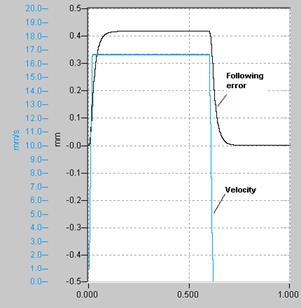 Fig.3: Following error without feedforward control
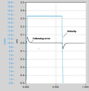 Fig.4: Following error with velocity feedforward control
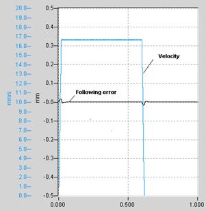 Fig.5: Following error with velocity and acceleration feedforward control