Process Image
Addressing with the BOOTP/DHCP Server 2.3
Switch the rotary switch to 0xF5.
The MAC Address begin with 00-01-05-xx-xx-xx ( the MAC address of each IL230x-B905 is printed on the right side of the box).
After a successful addressing you can disable the BOOTP addressing.
Open RSLogix 5000 and Create a new PLC project
When creating a new project make sure to select the correct controller type and controller settings. In this example we are using a SoftLogix Virtual Chassis, with the IL2301-B905 (Beckhoff Ethernet/IP Coupler Box)
Add Ethernet IP Module
Now you need to add your main communications module. Make sure you know the IP address of the card that is setup as the EtherNet IP card, that address will have to be set in the module settings along with the slot the card is in.
Add Ethernet IP Box
When adding the IL2301-B905 box you must select the "ETHERNET-MODULE" as it is a generic Ethernet/IP device and we will configure it to work with our Coupler Box.
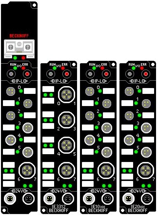
The figure below illustrates the hardware of the Beckhoff node in this example.
The process image table (I/O map) is displayed in double word format below the figure.
In order to properly configure the Ethernet Bridge, the process image of the Beckhoff IL2301-B905 node must be determined. When the Coupler Box is powered up, it automatically addresses the I/O modules of the node. The data for complex modules (modules using 2 or more bytes) are mapped first in the process image in the order of their physical position after the coupler. As such, they start at Double word 3. Following this, the digital modules are grouped into the next available Integer. The bits are arranged in the order of the modules location. When the number of digital points exceeds 32 (1-double integer), the coupler automatically starts the next Double Integer. THe Coupler Box itself has 4 digital input and 4 digital output bits. These shall not be forgotten, when looking for the signals in the data image!
Note: The modules can be mapped as Byte, Word, or Double Word. The example below maps them as Double Word, using 1 analog input module (IE3312), 1 digital input module (IE1001) and 1 digital output module (IE2001).
Input Process Image
• Double Word 0 - IL2301-B905 Status
• Double Word 1 – Channel 1 IE3312 (High Word) and Status (Low Word)
• Double Word 2 – Channel 2IE3312(High Word) and Status (Low Word)
• Double Word 3 – Channel 3IE3312(High Word) and Status (Low Word)
• Double Word 4 – Channel 4IE3312(High Word) and Status (Low Word)
• Double Word 5 – digital inputs IL2301-B905, IE1001
Output Process Image
• Double Word 0 - IL2301-B905 Status
• Double Word 1 – Channel 1 IE3312 (High Word) and Control (Low Word)
• Double Word 2 – Channel 2IE3312(High Word) and Control (Low Word)
• Double Word 3 – Channel 3IE3312(High Word) and Control (Low Word)
• Double Word 4 – Channel 4IE3312(High Word) and Control (Low Word)
• Double Word 5 – digital ouputs IL2301-B905, IE2001
Configuring the IL2301-B905 in RSLogix
For the example here we used one IE3312, one IE1001 and one IE2001 extension boxes. With these cards that gave us 2 words total of input and output data. On the properties dialog you will need to change some of the box settings, please read below for recommendations on settings.
- IP Address (Refer to IP Address section of documentation)
- The Assembly Instances will be as follows
- Input: 101
- Output: 102
- Configuration: 100
- Things to keep in mind when entering the data size for I/O
- There will always be 4 bytes of input and 4 bytes of output data that is used for the Coupler itself
- Digital IO: each channel will consume 1 bit of process data.
- Complex IO: please refer to terminal documentation for consumed data size.
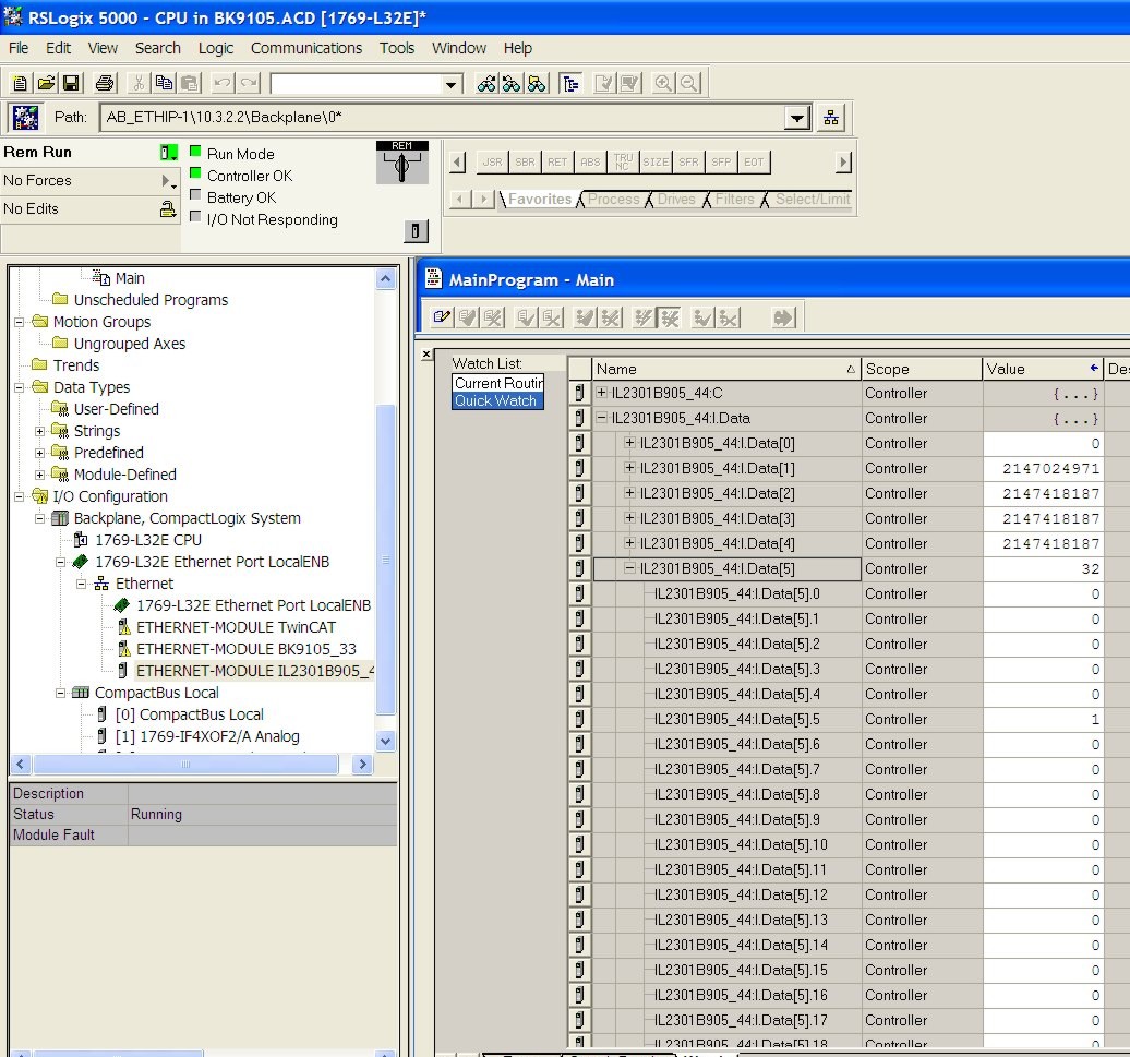
Working with IO data
Download the code to the controller unit, once you go online you will be able to toggle IO. Keep in mind that the first DINT is the Status for both the input and output data. At this point if you have the controller in RUN mode you will be able to toggle inputs and see the value in "IL2301B905_44:I.Data[5]" change and you should be able to update the values in "IL2301B905_44:O.Data[1]" and see the outputs change. Data[1] to [4] are the Status und Data form the 4 channel analog input module IE3312.
"IL2301B905_44:I.Data[5].5" is the second digital channel on the IE1001 (do not forget the 4 Bits for the IL2301-B905)