Diagnostic LEDs for Ethernet
After switching on, the Fieldbus Box immediately checks the connected configuration. Error-free start-up is indicated when the red I/O ERR LED goes out. If the I/O ERR LED blinks, an error in the area of the Inputs/Outputs is indicated. The error code can be determined from the frequency and number of blinks. This permits rapid rectification of the error.
The module has two groups of LEDs for the display of
status.
The upper group with four LEDs indicates the status of the
respective fieldbus. The significance of the fieldbus status LEDs
is explained in the appropriate sections of this manual. It
corresponds to the usual fieldbus display.
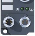
At the lower end of the Module are two more green LEDs that indicate the supply voltage. The left hand LED indicates the presence of the 24 VDC supply for the Fieldbus Box. The right hand LED indicates the presence of the supply to the power contacts.
LEDs for power supply diagnosis
|
LED |
In |
Out |
|---|---|---|
|
LINK |
Physical connection present |
No physical connection present |
|
ACTIV |
Flashing: Bus traffic present |
No bus traffic (bus idle) |
|
ERROR |
The LED flashes slowly if DHCP or BootP is active
but the Bus Coupler has not yet received an IP address |
No error. |
|
|
ON, when the box receives more than one Ethernet frame per module cycle. The master sends to fast! |
|
|
WD |
Out - Watchdog error or no communication |
- Start communication |
|
On - Watchdog works |
No error |
LEDs for power supply diagnosis
|
LED |
Meaning |
|---|---|
|
Left LED off |
Module has no power |
|
Left LED red |
Short circuit detection for sensor supply (< 500mA) is active. Sensors/Inputs are not supplied anymore |
|
Right LED off |
No 24 VDC power for the outputs connected |