Wiring the IP-Link
IP-Link is the subsidiary bus system for Fieldbus Boxes. Topologically, it is a ring. The IP-Link master is located in the Coupler Box (IL230x-Bxxx or IL230x-Cxxx). The extension boxes (IExxxx) are slaves. A maximum of 120 extension boxes may be connected. Additionally the available address range of the according Fieldbus Box coupler has to be considered. The distance between two extension boxes may not exceed 15 meter. When planning and installing the extension boxes, note that the last extension box in the optical fiber ring must be connected to the coupler box.
Structure/Topology
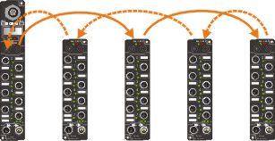
Line structure
In this case only every second extension boxes is connected. Note here that the maximum distance of the last extension box is halved.
Example
You have 4 extension boxes (4 x 15 m = 60 m). Because only every second extension box is connected to the outward line, the maximum distance for the last extension box becomes 30 meter.
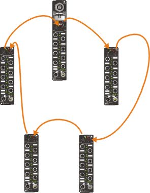
Ring structure
In this case the first and last extension box must each be no more than 15 meter from the Coupler Box.
Technical Data
|
|
IP-Link |
|---|---|
|
Baud Rate |
2 Mbaud |
|
Medium |
Light |
|
Number of devices |
max. 120 |
|
Distance between two stations |
15 m |
|
Cable |
Plastic optical fiber 1000 um - single fiber core, PUR cladding with Kevlar fiber, diameter 5.5 mm |
|
IP link connector |
only ZS1020-0010 is permitted |
|
Extraction force |
20 N - 30 N |
|
|
Z1101 |
|---|---|
|
Nominal external diameter |
5.5 mm |
|
Cladding thickness |
1.4 mm |
|
Fiber |
Plastic fiber optic 980/1000 µm, PMMA |
|
Core |
PE cladding, 2.2 mm nominal diameter |
|
Temperature |
-20...+70°C |
|
External cladding material |
PUR |
|
Nominal weight kg/km |
25 |
|
Tensile strength |
Continuous 100 N |
|
Bending radius |
Radius minimum 50 mm |
|
Alternating bending strength (DIN VDE 0888 Part 100 Procedure 509) |
30,000 cycles |
|
drag chain approval |
Radius 10 x diameter, 2 Mio. cycles |
|
Attenuation at 650 nm |
< 200 dB/km |