Diagnostic LEDs
After switching on, the module immediately checks the connected configuration. Error-free start-up is indicated when the red I/O ERR LED goes out. If the I/O ERR LED blinks, an error in the area of the terminals is indicated. The error code can be determined from the frequency and number of blinks. This delivers a fast error elimination.
The module has two groups of LEDs for the display of
status.
The upper group with four LEDs indicates the status of the
respective fieldbus. The significance of the fieldbus status LEDs
is explained in the appropriate sections of this manual. It
corresponds to the usual fieldbus display.
At the lower end of the Module are two more green LEDs that indicate the supply voltage. The left hand LED indicates the presence of the 24 VDC supply for the Fieldbus Box. The right hand LED indicates the supply voltage of the outputs.
The LEDs ACT and ERR are reserved and have no meaning at this time.
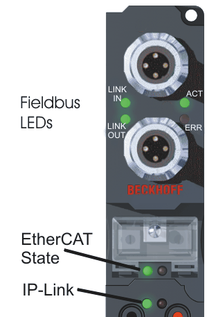
LEDs for fieldbus diagnosis
|
LED |
Display |
Status |
Meaning |
|---|---|---|---|
|
LINK IN |
off |
- |
no connection with the previous EtherCAT client |
|
on |
linked |
previous EtherCAT-client connected | |
|
blinking |
active |
communication with the previous EtherCAT client | |
|
LINK OUT |
off |
- |
no connection with the next EtherCAT client |
|
on |
linked |
next EtherCAT client connected | |
|
blinking |
active |
communication with the next EtherCAT client | |
|
ACT |
- |
- |
reserved |
|
ERR |
- |
- |
reserved |
LEDs for EtherCAT State Machine / PLC diagnosis
|
LED |
Display |
Status |
Meaning | |
|---|---|---|---|---|
|
RUN |
green |
off |
Init |
State of the EtherCAT Fieldbus Box: INIT = Initialization |
|
blinking |
Pre-Operational |
State of the EtherCAT Fieldbus Box: PREOP = Pre-Operational | ||
|
single flash |
Safe-Operational |
State of the EtherCAT Fieldbus Box: SAFEOP = Safe-Operational | ||
|
on |
Operational |
State of the EtherCAT Fieldbus Box: OP = Operational | ||
|
flickers |
Bootstrap |
State of the EtherCAT Fieldbus Box: BOOT = Bootstrap (Update of the coupler firmware) | ||
|
ERROR |
red |
off |
- |
no error |
|
blinking |
Err-Operational |
PLC error / Lost Frames | ||
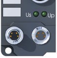
LEDs for power supply diagnosis
|
LED |
Meaning |
|---|---|
|
left LED off |
Module has no operating voltage |
|
left LED red |
Short circuit detection for sensor supply has released (> 500mA). Sensors / inputs are not supplied. |
|
right LED off |
No power supply 24 VDC for outputs connected |