Troubleshooting
If there are errors on the cable length, we recommend the following procedure:
- Install a substitute cable instead of the installation cable and test the operation.
The substitute cable should have a proven and renowned quality and should be handled carefully.
The substitute cable must not lay parallel to the investigated installation cable, an appropriate distance to the former conduit should be kept.
The shielding of the substitute cable should be new, and, if applicable, connected to other connection points.
The max. allowable length of cable relating to the line attenuation must be noted.
- If you can establish an operation with the substitute wire, a stepwise localization of the error cause is possible:
- post-measurement of the installation cable -> certification
- cable routing
- transition points
- shielding/shielding connection
Interpretation of certification results
- ‘Attenuation’ errors usually come from the cable: too long/attenuation too high.
- ‘NEXT’ errors usually come from the plug: not correctly contacted, untwisted too far.
- Differences in the DC resistance between individual pairs --> cables damaged, poor contacting
- ‘RL’ errors can come from a poorly contacted plug.
- RL errors can come from an internally damaged cable in a moving application.
- Knots in the Ethernet cable affect the characteristic impedance!
 | FastEthernet & cable parameters In the case of 100 Mbit Ethernet, only one of 4 pairs (if available) is in operation for transmission and one for receiving, and not often at the same time – crosstalk effects depend among other things on the extent of utilization (no. of frames, frame lengths vs. cable lengths). In particular in the case of 1 GBit Ethernet and upwards, the specified parameters become important due to the simultaneous and bidirectional operation of the pairs. |
Practical experience
- Incomplete cable screen
The cable is only shielded in sections ex-works or is manufactured with insufficient coverage according to EN50288/EN50290. - Field-configurable plug does not fit the cable used
If the core diameter is too small, the insulation displacement contact may not penetrate to the metal conductor and may only cut a little into the insulation. - Compatibility
RJ45 plugs and sockets are not functionally compatible despite normative requirements and are prone to intermittent contacts. - Wall feed-throughs without earth contact
if a metallic double coupler is used as a wall feed-through into a painted housing, the screen contact for system earthing is missing. - Wrong assembly tool
Crimping tool and RJ45 plugs should be approved together by the manufacturer. - Cable damage
An unsuitable cable can be damaged by repetitive movement; this may not be outwardly visible.
Example – incompatible plug connection leads to intermittent contact
In the following example, the contacts in the plug are so short that the spring contacts in the socket are pushed beyond the reliable contact point when the plug/socket connection is pushed fully together. This may already be noticeable during the WireMap measurement as a broken core.
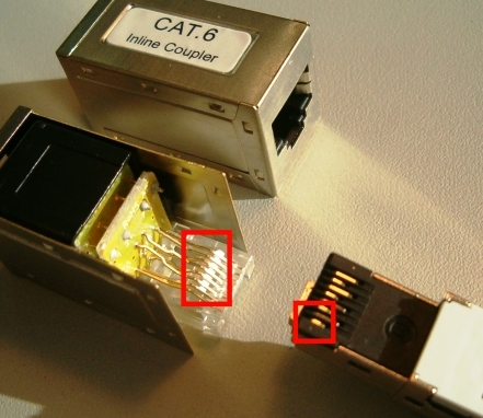 Fig.39: Field-configurable plug, double coupler
 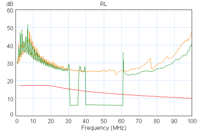 Fig.40: Effect of the intermittent contact during the return loss measurement
 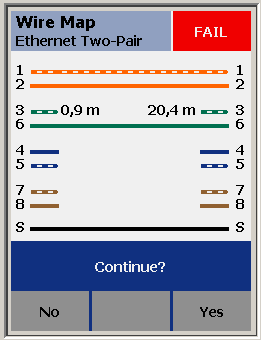 Fig.41: WireMap error due to the double coupler after 1 m of device connection cable
 Example 2 - fixture for diagnostic testing
In the following example, a fixture was built in order to specifically generate transmission errors in the Ethernet cable for test purposes. The setup is, however, most disadvantageous for the transmission performance due to the disregard of the high frequency aspects addressed and the use of components not suitable for HF, and is immediately noticeable in the test. It is thus possible that the transmission link may not work even with short cable lengths. In detail:
- Interruption of the screen, construction is not in a screened housing
- Parallel untwisted routing of the cores over many centimetres
- Plug connection and switching elements unsuitable for HF
- Solder track layout unsuitable for HF
- No fixing of the cores, measurement results not reproducible
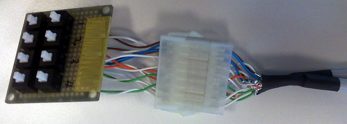 Fig.42: Fixture for insertion into the transmission cable
 | Change of the transmission link Exclusively suitable components that have been correctly installed/connected according to the manufacturer’s instructions should be used in Ethernet transmission links. The transmission link should be certified in each case. |
Example 3 – poor execution of the cable/connector connection
In the following example, the core pairs are untwisted over an unnecessarily long distance contrary to the manufacturer’s instructions; therefore local crosstalk is very much facilitated. In the test, such a connector is noticeable by a high crosstalk and/or a low crosstalk attenuation “NEXT”.
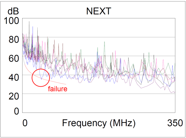 Fig.43: Result of the NEXT test
 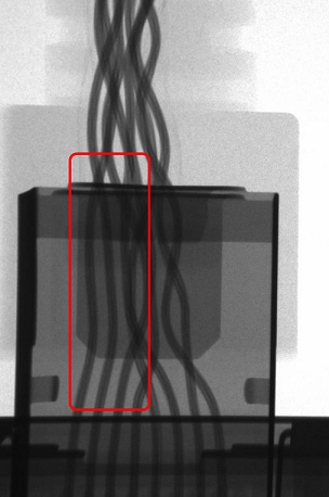 Fig.44: X-ray picture of an RJ45 connector