Remarks regarding shielding
The IEC61158-2 standard and in particular the IEC61784-5 EtherCAT installation profile demand a fully shielded cable for EtherCAT transmission links. This also corresponds to the general state of the art for communication cables. Twisting and differential transmission in the so-called twisted pair medium provide for fundamental interference immunity, while an overall shield around the transmission link supports the interference-free transmission of data. Over and above that, even single-pair shielded cables are used in higher connection classes (Cat6, Cat7).
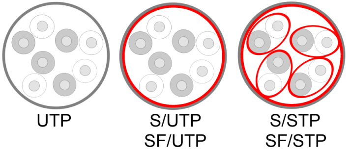 Fig.29: 4-pair cable structure: unshielded UTP, overall shielded S (F)/UTP, overall shielded and shielded pairs S (F)/STP
 The following notes correspond to the state of the art. VDI guidelines, EN/IEC standards or EMC guidebooks can be consulted as sources.
 | This document This document provides general recommendations based on practical experience, without taking into account specific features of particular installations. These recommendations should be regarded as a collection of technical solution options. System manufacturers should check to what extent the measures described here are applicable to their system, and which of the suggested measures should be implemented. To this end, different measuring and testing techniques should be used. Any problems should be examined thoroughly, in order to ascertain the trigger and the fault location. |
- The overall shield around the core pairs provides for protection against external electromagnetic interference fields for the enclosed communication cores.
It is important for effectiveness that the shield coverage has a low impedance throughout and that it is also implemented without interruption or holes at transition points (EN50174-2:2009, chapter 4.7). Holes in the sense of this documentation are uncovered areas of the order of centimeters. - The shield should be connected at each end of the cable to the machine earth via an electrically conducting connection with a large surface area and low impedance. A pigtail, i.e. the twisting together and point contact of the shield, must be avoided. However, this can lead to circulating currents. In such cases, a one-sided RC connection (combination resistor/capacitor) makes sense.
- If the shield is not earthed, there is no protection against the influence of magnetic fields.
- It must be ensured by means of sufficient parallel earthing or RC connection in the plant that no equalizing current flows via the shields of the communication cables. This can destroy connected devices.
Ethernet devices can therefore connect the shield to ground internally with an RC combination. Static equalizing currents are this prevented, while high frequency interference is eliminated.
To support this, therefore, the shield of the communication cable should additionally be earthed with a low impedance at the control cabinet entry point and, if necessary, on the device itself by suitable means.
Beckhoff offers appropriate installation material in the ZB8500 product group. - Shield contacting should also be present at transition points (e.g. plug -> cable, couplings) and should encompass them 360°.
- The shield material is not to be used for strain relief.
- Suitable materials, preferably copper, are to be used as shield material. If aluminum is used, the special characteristics of aluminum must be considered.
Note: in the case of foiled versions, the foils for Industrial Ethernet are usually made of aluminum. - The “coupling attenuation” shielding effect, i.e. the qualitative effectiveness or implementation, can hardly be reliably measured in the field or with the cable laid. The usual measuring instruments/certifiers are limited to a static continuity measurement. Beyond that, however, there are well-known and standardized laboratory-assisted measuring methods, such as the pipe-in-pipe or drain wire methods, which can also determine the high frequency characteristics and the attenuating behavior of the shield and in this way make it possible to check adherence to a coupling attenuation of >40dB (EN50174-2:2009, 30-100 MHz). However, these are uneconomical for industrial series and field use. Therefore, perfect workmanship must be ensured in the execution from the outset.
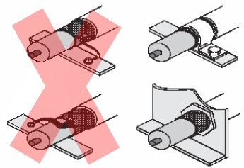 Fig.30: Recommended shield connection
 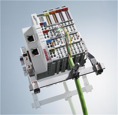 Fig.31: Correct shield connection
 An inadequate shielding effect may become visible by transmission errors. The diagnostic means in the EtherCAT Master TwinCAT and the EtherCAT Slaves permit the continuous, in-depth location of such defects. Observe the notes in the EtherCAT system documentation regarding this.
| Optical fiber cables/optocouplers The use of Ethernet optical fiber cables between the components may provide a solution in difficult EMC environments. |