Total transmission link
General Ethernet copper cabling (twisted pair) according to BS EN 50173 is characterized by:
- Max. 90 m permanently installed cable (as per EN50288-x-1) + two max. 5 m device connection cables (as per EN50288-x-2), altogether 100 m
- Max. 4 plug connections between the end points + 2 terminal connectors
- Cable according to EN50288
- Double couplers (for the connection of two RJ45 plugs) are treated separately and normally count as 2 plug connections.
- All cables must exhibit the same nominal characteristic impedance: 100 ±5 Ω or 120 ±5 Ω @ 100 MHz.
- Optionally existing overall cable screen or additional core pair screening. It is recommended that exclusively screened cable be used for EtherCAT.
The sections of a transmission link are discussed on the basis of the following illustration:
 Fig.4: Transmission link
Model A:
Model A illustrates the maximum permissible model according to EN50173-1, consisting of
- max. 90 m permanent link: permanent link with cable according to EN50288-2-1
- Total of 6 plug connections C, including the terminal connection points
- max. 2 x device connection cables as per EN50288-2-2, ‘Patch cables’
Decisive for acceptance tests is that
- a measurement of the permanent link according to EN50173-1, appendix A includes the two connection points
- a measurement of the channel according to EN50173-1, chapter 5 does not include the two connection points
The target market of ISO11801/EN50173 ‘Building network-orientated cabling’ becomes clear from the structure (patch bays, intermediate distributors, floor distributors). The maximum of four plug connections can also be distributed in other ways over the cable section, for example in patch bays; see Model B.
Model B, C:
Models B and C represent more typical transmission links for the industrial area; they are discussed in EN50173-1 or ISO24702.
Connector
A transition point negatively affects the entire transmission link due to attenuation, reflection and crosstalk between the cable pairs. Therefore the number of permissible transition points for a channel conforming to EN50173 is limited to six.
A plug connection (obj. C in Fig. “Transmission link”) represents one transition point between the two elements plug/socket.
 Fig.5: Simple plug/socket transition
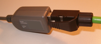 Fig.6: Pic: Simple plug/socket transition
A double coupler thus represents 2 transition points, unless it is specified by the manufacturer as 1 transition point in the sense of plug connectors.
 Fig.7: Double coupler
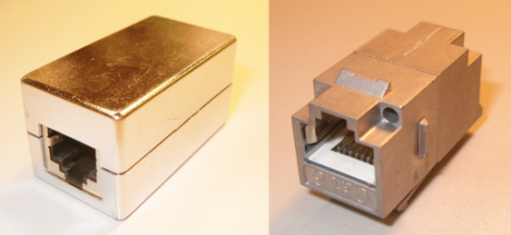 Fig.8: Double couplers; left Cat. 5, plastic; right: Cat. 6, all metal
Since only double couplers of at least Cat. 6 are permissible (EN50173-3, Appendix B) for the maintenance of the EN50173 Class D performance of a transmission link for which only Cat. 5 components are normally demanded, preference is to be given, for example for wall feed-throughs, to those with a simple plug/socket transition.
Performance of a transmission link
EN50173-1:2007, chapter 5 defines 8 classes according to the permissible frequency range:
Class | Frequency range |
|---|---|
SRKG | up to 0.1 MHz |
A | up to 100 kHz |
B | up to 1 MHz |
C | up to 16 MHz |
D | up to 100 MHz |
E | up to 250 MHz |
F | up to 600 MHz |
RuK-S | up to 1000 MHz |
Equations according to which the frequency-dependent limit curves (e.g. within the range 1 to 100 MHz, class D) can be calculated are specified for the Ethernet-relevant performance classes D, E and F. Depending on the parameters, the measured value must remain, if necessary as f(f), under or above the limit value curve.
 Fig.9: Examples of measurements: Insertion loss and NEXT – frequency-dependent limit curve shown in red in each case
The following parameters are defined:
German | English | Abbreviation |
|---|---|---|
Rückflussdämpfung | Return Loss | RL |
Einfügedämpfung | Insertion Loss, Coupling Attenuation |
|
Nahnebensprechdämpfung | nearend crosstalk loss | NEXT |
leistungssummierte Nahnebensprechdämpfung | powersum NEXT | PSNEXT |
Dämpfungs-Nebensprechdämpfungs-Verhältnis, nahes/fernes Ende | Attenuation to crosstalk ratio near/far | ACR-N ACR-F |
Leistungssummiertes ACR | powersum ACR | PSACR |
Ausgangsseitige Fernnebensprechdämpfung | equal level far end crosstalk ratio | ELFEXT |
Leistungssummiertes ELFEXT | powersum ELFEXT | PSELFEXT |
Gleichstrom Schleifenwiderstand | Resistance | - |
Gleichstrom Widerstandsunterschied | Resistance Difference | - |
Laufzeit | Propagation Delay | - |
Laufzeitunterschied | Delay skew | - |
TCL Unsymmetriedämpfung | Transverse Conversion Loss | TCL |
Kopplungsdämpfung |
| - |
Not all parameters are obligatory for each performance class; measurements must be performed in accordance with EN50346.
Extract from characteristic values EN50173 Class D
|
Characteristic value |
Channel |
Permanent Link |
|---|---|---|
|
Length [m] |
max. 100 m |
max. 90 m |
|
max. insertion loss [dB @ 100 MHz, 100m] |
24 dB |
20.4 dB |
|
NEXT [dB @ 100 MHz, 100m] |
30.1 dB |
32.3 dB |
|
max. propagation delay [ns @ 100MHz] |
548 ns |
491 ns |
Remarks:
- in the (informative) calculations of the max. limit values in EN50173-1, chapter 5.2, the max. permissible 4 plug connections within the channel are assumed
- EN50173 class D permits a max. signal propagation delay of 548 ns at 100 MHz – this limits the use of excessively long cables. The channel length is already limited to 100 m at an assumed NVPcable of 60%.
- All limit values are based on an assumed ambient temperature of 20 °C. A derating (0.2%/°C) is defined in EN50173 up to the region of 60 °C: the cable/plug characteristics worsen as the temperature increases; therefore, the max. permissible channel length decreases as the temperature increases.
 | Deviation from the specifications The specifications of ISO11801/EN50173 quoted above can be deviated from, e.g. by more plug connections or cable sections than permissible or by non-conforming cable material. In this case the transmission link must be calculated according to ISO11801/EN50173 and verification/certification is recommended after the installation. |
Notes on device connection cables
The usual method for the acceptance testing of device connecting cables/patch cords is the patch cord measurement using special patch cord adaptors (e.g. Fluke) and the patch cord limit values according to EN50173.
Max. 20 m are specified; the attenuation is therefore not specified.
Only RL and NEXT are measured; these are worded more strictly than in the channel.