Summary
The market is growing for Ethernet as a physical medium for the transport of real time fieldbus protocols in the industrial environment. Unfortunately, knowledge of this technology is not growing at the same rate as the enthusiasm for it, even among EtherCAT users. So that basic network principles from the office area are not applied unreflected to industrial concerns, it is necessary to sensitize planners and users to the technological aspects.
As a real-time protocol, EtherCAT relies on Ethernet as a physical carrier, and is thus dependent on the long-term stable operation of the Ethernet connection.
As with other fast transmission systems, disruptive effects can also occur with the high frequency Ethernet technology in operation or during commissioning if it is used inappropriately. These disruptions are simple to locate or avoid completely if a few basic principles are followed.
This documentation is intended to provide users with a guideline, without any obligatory character or legally binding effect, to enable them to plan, install and check reproducibly reliable Ethernet cabling in the industrial environment.
This document makes no claim to be complete and, in particular, does not replace normative installation directives such as IEC 61784, fundamental communication directives such as IEC11801/EN50173 or specific installation directives. This document is mainly intended for the European market. Therefore, reference is mainly made to European EN standards. The globally important ISO/IEC (International Electrotechnical Commission, www.iec.ch) standards are often identical in content to corresponding EN standards.
In addition, the ETG guideline ETG.1600 provides comprehensive and concrete guidance on the cabling of EtherCAT systems.
Based on the following chapters, the fundamental information can be summarized as follows:
- An Ethernet transmission link (channel) is characterized by a (technically related) capability to reliably guarantee a defined data throughput [Mbit/s] under all defined operating conditions and, hence, high service quality.
- These performance classes are defined for Europe in the EN50173-1 standard, e.g. ‘Class D’. If a transmission link verifiably corresponds to a performance class, then it conforms to EN50173. A component manufacturer (cable, connector) can certify its products according to the limit values from EN50173 et al. The exclusive use of components certified to EN50173 may be sufficient to ensure the conformity of the transmission link; in individual cases it must be verified by means of suitable measuring methods according to EN50346.
- A transmission link for the transmission of Ethernet telegrams can be implemented according to the requirements of these application-independent standards; however, it does not have to be, in which case it is application-specific cabling. Experience has shown that cabling that lies far outside the normative specification also (sometimes) works.
- It is recommended that agreement be reached between suppliers and users on the properties and acceptance procedures with regard to the Ethernet cabling used.
- Borderline Ethernet cabling can work reliably under acceptance conditions, but fail under operating conditions (aging, EMC, temperature, movement/impact).
- Distinction must be made between Ethernet components certified according to
- European standard series: EN50173 (similar to IEC11801)
- US standard series EIA/TIA 568
The two standards differ slightly and also still use the same terms, such as “Cat 5” or “Class D”. But: components certified according to TIA568 may not be used in cabling installed according to EN50173. In most cases no complications arise, but the cabling or the entire installation section is no longer compliant with the EN standard [EN50173-3, chapter 1]. - As a globally used communication protocol, the ISO/IEC 61918 standard and the ISO/IEC 61784-5 EtherCAT installation profile are authoritative for EtherCAT. These contain definitions themselves or are based on other ISO standards.
In Europe, the EN standards mainly referred to in this document can be applied. The European member states maintain these EN standards as country-specific standards. Hence, the EN standards are called “DIN EN” in Germany. Since the technical specifications mentioned in the ISO/IEC standards are usually based on the general consensus of the professional technical world, most ISO/IEC specifications are to be found in a similar form in the EN standards. A comparison is not part of this documentation. - Extended standard series (ISO24702, EN51918 et al.) have been drawn up especially for industrial concerns and deal with environmental conditions or with protocol-specific regulations, for example. However, they do not affect the basic electro-technical principles according to EN50173.
- The performance (i.e. the reliable transmission of 10/100/1000 Mbit/s) of Ethernet cabling generally depends on the following factors:
- the cable quality (attenuation, cross-section, cable structure, screening) of the individual subsections
- the plug quality (fit, screening, cable suitability)
- the number of intermediate connections
- the ambient temperature (20 to 60 °C, specified with derating according to EN50173)
- Environmental influences (e.g. MICE classification according to EN50173-1, chapter 5: Mechanical/Ingress/Climatic/Electromagnetic rating) - In the EtherCAT application area, only the connection performance of 100 Mbit/s FastEthernet according to EN50173 Class D [up to 100 MHz] is required and is dealt with below. It is permissible for the user to demand connection classes with a higher performance (classes E [up to 250 MHz], EA, F [up to 600MHz MHz], FA), but this is not technically justified.
- In order to achieve this performance class, only Ethernet components conforming to EN50173 Cat. 5 (minimum) are permissible; see EN50173-3, chapter 1.2, among others.
Components according to EN50173 Cat. 5 are sufficient, but when using wall feed-throughs/double couplers, these must conform to EN50173 Cat. 6 in order to achieve performance class D. - This document deals at present only with copper-based Ethernet 100Base-TX cabling, not fiber optic cabling according to 100Base-FX.
- 4-core/2-pair cables are favored in Industrial Fast Ethernet, as opposed to the fully assigned 8-core/4-pair cables normally used in building automation. This is to be considered during the acceptance test (see there).
- The recommended assignment of a 4-core/2-pair industrial Ethernet cable is the 1,2,3,6+ screen configuration based on TIA-568A.
- The following is recommended for the cable cross-sections:
- Wire structure: stranded or rigid core
- Cross-section: AWG26/7 to AWG22/1 accordingly 7 cores 0.14 mm² (stranded) up to 0.34 mm² rigid. - According to EN50173-1, the maximum permissible configuration for an Ethernet link is 90 meters of permanently installed cable plus 2 device connection cables of 5 metres each, with a maximum of four intermediate connectors. Other configurations, such as a direct 100 m long connection, are to be designed in accordance with EN50173-3, appendix B and tested in the field for conformity to the performance class.
- Caution when using expressly patch cables/cords: commercially available patch cables up to approx. 10 m are subject to considerably more generous limit values as per EN50173-1, chapter 9 than cables that are intended for permanent installation as per EN50288. Series connection or an over-length configuration is to be avoided and, if necessary, checked at least by verification – a simple continuity test is not sufficient! Application-specific patch cables manufactured from appropriate goods sold by the meter are also to be checked for their suitability.
- The number of plug connections between the end points is to be reduced to the necessary minimum.
- It is recommended to use exclusively screened Ethernet cables as per EN50288-2 (STP, SF/UTP). Together with the special twisted pair execution, the cable screen is instrumental in preventing the interspersion of interference into the communication cable and thus ensures the reliable operation of the communication link. The terminal devices must support the screen connection.
In particular when using field-configurable connectors, it must be ensured that there is a technically perfect, state-of-the-art screen connection between the connector and the cable (see also EN50174-2 and general VDE screening regulations). The qualitative testing of the screening effect is only possible in the laboratory at present (2011). Therefore, perfect workmanship must be ensured in the execution.
- There must be 360° screen contact at all transitions. Pigtails (twisting the screen braid together before the contact) are not permitted.
- The screen contact must also be guaranteed on a long-term basis (mechanical or chemical influences).
- Interruptions and small holes in the screen must be avoided.
- The cable screen must not be used for strain relief.
- The screen material must meet the electrical and mechanical requirements. Special cables are to be used for drag chains or garlands.
The instructions of cable and connector manufacturers are to be observed. - The employment of rigid Ethernet cables instead of stranded wires is recommended where possible on account of the better electrical properties (Attenuationstranded > Attenuationrigid).
- It is recommended to employ larger core cross-sections if possible, (e.g. AWG22 instead of AWG26) on account of the better electrical characteristics (Attenuationthin core > Attenuationthick core). If the length exceeds 50 meters, too small a cross-section (AWG26) can prevent conformity to the performance class!
- It is recommended to check the installed Ethernet cabling before commissioning.
- It is recommended to monitor installed Ethernet cabling during operation using a means of software diagnosis (e.g. Beckhoff TwinCAT).
In accordance with the specified standards, a verification decision on a cable section can thus be made as follows:
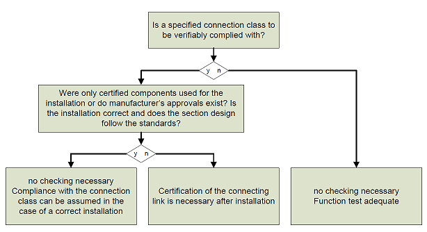 Fig.1: Verification decision