Setting up - SyncUnits setup
SyncUnits only have to be created if failure of an EtherCAT slave is to be expected.
 | Cyclic data SyncUnits are only relevant for communication via cyclic data. Acyclic communication, e.g. via mailbox, is always controlled by the System Manager. |
By default the System Manager tries to integrate all I/O data in a few Ethernet/EtherCAT frames as possible, i.e. the System Manager tries to utilize the maximum frame size of 1518 byte per Ethernet frame or 15 datagrams. The aim is to achieve efficient and optimized communication with minimum load on the fieldbus.
A datagram is a telegram with exactly one read/write instruction. A datagram may be a read command over 2 bytes from an analog input terminal or a write command for 400 bytes of data to 10 servo drives.
 Fig.240: Structure of an Ethernet frame with EtherCAT protocol data
This is illustrated in Fig. Structure of an Ethernet frame with EtherCAT protocol data: the Ethernet frame (row 1) consists of a header (blue), data (yellow) and the checksum CRC (blue). If the Ethernet frame carries EtherCAT protocol data, these data also consist of an EtherCAT header (red) and 1 to 15 datagrams (green). The latter consist of a header, data and a WorkingCounter (WC).
The working counter is the key parameter for the cable redundancy principle. The working counter is a 16-bit number sent by the EtherCAT master with the value "0". Each EtherCAT slave that is accessed by this datagram in write or read mode increases this number by 1, 2 or 3, depending on the type of access. Once the datagram has run through the complete configuration, the working counter therefore returns to the master with a value greater than 0. The master expects a certain value, because it knows how many slaves have to process this datagram. If the WC returned by the datagram does not match the expected value, one of the slaves did not fulfil its task. The master then has to employ special measures in order to establish which slave is affected and whether the datagram has to be repeated.
The frame structure of the cyclic data based on the current configuration can be viewed in the TwinCAT System Manager (EtherCAT tab of the respective EtherCAT device).
Example for a small configuration:
 Fig.241: TwinCAT view, frame structure - small topology
Only one Ethernet frame is used for the cyclic I/O data (red), carrying 3 EtherCAT datagrams, i.e. 2x LRD (LogicalRead) and 1x BRD (BroadcastRead).
With 59 bytes of data the frame is 6.72 µs long and uses 0.17% of the cycle time of 4 ms.
The first datagram has an expected working counter of 1 and a BRD command of 2, see column WC.
In a larger configuration the frame structure becomes more complex:
 Fig.242: TwinCAT view, frame structure - larger topology
With a cycle time of 1 ms 3 Ethernet frames are in transit carrying a total of 9 datagrams with expected working counters between 3 and 52. This configuration uses 35.94% of the available bandwidth of 100 Mbit FastEthernet at a cycle time of 1 ms.
Application to the cable redundancy in the event of slave failure
If a datagram returns to the master with an incorrect working counter, the master is initially unable to determine which slave failed to deliver data. The master therefore has to declare all input data in this datagram invalid, i.e. in all affected slaves the WC indicator switches to 1=invalidData.
 Fig.243: WC = 1 indicates invalid data
The System Manager sets this WC indicator immediately on receipt of the datagrams for the respective slave. This is illustrated for an EL3162 in Fig. WC = 1 indicates invalid data, the input data are frozen, WcState = 1 and the State in accordance with the bit meanings of 0x0101 "Slave in INIT" and "Slave not present".
If an EtherCAT slave fails, e.g. an analog input box EP3174, this would mean other input data contained in the same datagram to make the frame structure efficient would also be discarded. As a remedy the user can manually assign each slave to a so-called SyncUnit. In extreme case each slave could have its own SyncUnit, with associated negative consequences for the fieldbus efficiency and excessive bus load.
The corresponding dialog is accessible via the EtherCAT tab, see Fig. TwinCAT view, frame structure - larger topology.
A slave is assigned to a SyncUnit, see Fig. Entering the SyncUnits in a default frame structure
- by clicking in the column
- Enter a name (any name) under SyncUnitNames
If a name is allocated more than once, the slaves are operated accordingly in a datagram (logical SyncUnit).
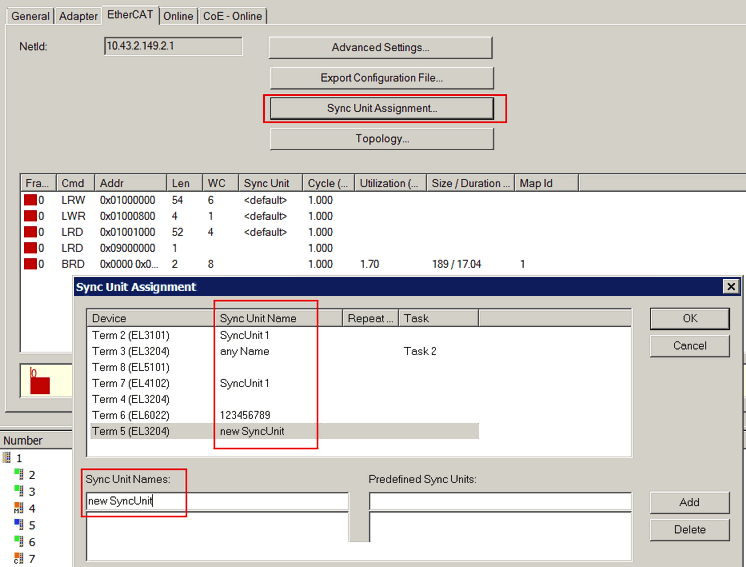 Fig.244: Entering the SyncUnits in a default frame structure
This results in a new structure of the cyclic Ethernet frame in accordance with Fig. New frame structure with SyncUnits:
 Fig.245: New frame structure with SyncUnits
The System Manager will continue to automatically consolidate devices that are not set manually in datagrams and may identify them as <default>.
Typically modules are defined as a separate SyncUnit and communicate via an Ethernet cable connection:
- EK11xx coupler including append EL/ES/EMxxxx terminals
- EP boxes
- AX drives
- ...
If the communication with such a station fails, only the data for this SyncUnit become invalid. The data exchange with all other stations remains unaffected.