Setup TwinCAT 2.11R2
The configuration dialogs under TwinCAT 2.11R2 are different, although the principle is the same as for TwinCAT 2.10.
Configuration parameterization
Alternatively, the EtherCAT configuration can be set up via an online scan or manually, as described below.
- 1. First set up a maximum configuration, i.e. the configuration should cover all bus coupler stations that could be used in the system, even if they are not all operated at the same time. The order and the associated “Previous Port” parameter are irrelevant.
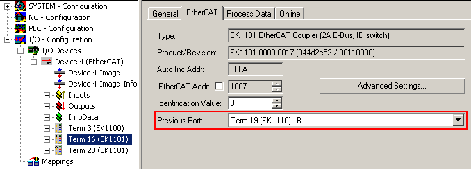 Fig.220: PreviousPort at bus station
 | HotConnect units Only units that communicate via Ethernet may be assigned an EtherCAT ID, because only these units can be connected or disconnected during operation. These are devices with RJ45/optical fiber/M8/M12 Ethernet port (couplers, EP boxes, drives, ...). Terminals may not be connected or disconnected while live. Specification as flexible HotConnect group therefore makes no sense. |
- 2. The designated flexible bus stations are assigned the HotConnect characteristic in the System Manager. The dialog is called up by right-clicking on a coupler station/EP box.
- 3. In TwinCAT 2.11R2 a coupled bus station can be identified as the “right” one via two properties:
- the ID “identification value”
- the EtherCAT address of the previous slave
Activate the associated characteristic and specify the value [0; 65535]. The ID refers to identification through InputWord and SecondSlaveAdress. The default setting is InputWord. To use SSA proceed as follows.
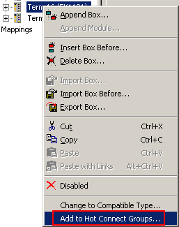 Fig.221: Calling up the HotConnect dialog
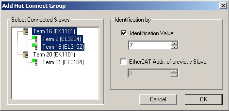 Fig.222: HotConnect features
 | Identification via “previous slave” If "previous slave" is specified as the address, a bus station parameterized in this way can no longer by inserted and operated at any port, but only at the specific EtherCAT port that follows directly after the specified slave. This method therefore significantly restricts the location of such a station. “Previous” refers to the preceding slave in terms of the EtherCAT communication, not necessarily the actual order in the topology. This is particularly relevant for the EK1122/EK1521 multi-port slaves. |
- 4. The station then has an additional “HotConnect” tab, in which the attributes can be modified.
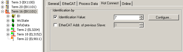 Fig.223: HotConnect features
Under Properties, the InputWord default identification (from the “DataWord” dialog under process data) can be changed to SecondSlaveAdress via Configure (in dialog “Configured Station Alias” from slave register 12hex).
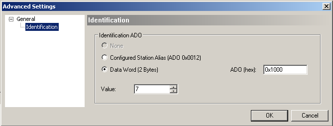 Fig.224: Setting detail
 In the System Manager the device is identified with a red HotConnect icon.
| Identification via “Data Word” The 16 bit identification data are read from the slave at a specified location. TwinCAT 2.10 only supports register 1000hex. TwinCAT 2.11 can read from any location, as shown in the dialog in Fig. Setting detail “ADO (hex)”. The default setting is register 1000hex or the specification from the ESI file. |
HotConnect operation
For HotConnect operation TwinCAT must be in Config/FreeRun or RUN mode. After changes in the configuration (other ID, ID location etc.) the configuration must be reloaded or TwinCAT restarted.
Sample 1: Groups not identified but linked
If stations that have an ID are connected via Ethernet but are not yet identified, the respective slaves come up with status messages:
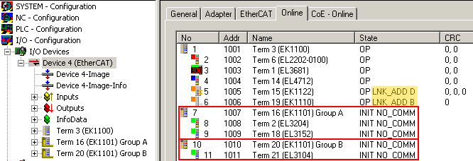 Fig.225: Status messages
- “LNK_ADD” together with the port information is shown for the slaves at which the stations were connected: this indicates an unsuspected LINK to unidentified devices.
- The stations themselves (in this case Group A, Group B) are still in INIT state. No communication is possible.
TwinCAT will keep trying to identify the coupled devices.
Sample 2: Group identified
The EK1101 “Group A” is now set to the right ID via the ID switches. After a few seconds TwinCAT recognizes this, includes the group in the process data traffic and changes the devices to OP state.
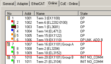 Fig.226: Group A in operation
The control system indicates this via the process data (WC state, state) of the coupler:
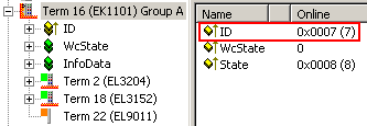 Fig.227: Process data of the ID module
Sample 3: Utilization of the topology view
The online topology view reflects the current actual link status and coupling location.
The offline view shows the ID stations without communication connection, since the connection locations are unknown.
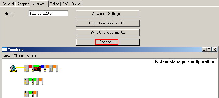 Fig.228: Offline view
 Stations that are not identified or present are shown in red in the online view.
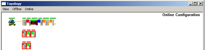 Fig.229: Online view
If stations are activated by changing the ID (here: switch setting at EK1101) the green OP bar appears.
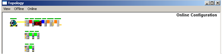 Fig.230: Online view
Switching to offline view and back updates the current connection status.
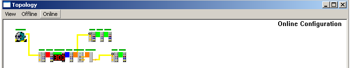 Fig.231: Current connection status