IO-Link access via PROFINET
Task
Connection of an IO-Link sensor to the ER9320-0022.
Configuration of the process data
Each IO-Link device is inserted as a submodule of the IO-Link master. A SubSlot is used for each IO-Link device. The process data sizes of the submodule must be equal to or greater than those of the IO-Link device.
If you are not using all IO-Link channels, insert a submodule "Empty Channel" in each of the unused SubSlots.
The first submodule of the IO-Link master is a diagnostic module. This submodule contains the status of all connected IO-Link devices. If an IO-Link device is in IO-Link data exchange, the corresponding byte contains the value 0x03.
Information on the status byte:
0x_0 = Port disabled
0x_1 = Port in std dig in
0x_2 = Port in std dig out
0x_3 = Port in communication OP
0x_4 = Port in communication COMSTOP / dig in Bit (only in std. I/O mode)
0x_8 = Process Data Invalid Bit
0x1_ = Watchdog detected
0x2_ = internal Error
0x3_ = invalid Device ID
0x4_ = invalid Vendor ID
0x5_ = invalid IO-Link Version
0x6_ = invalid Frame Capability
0x7_ = invalid Cycle Time
0x8_ = invalid PD in length
0x9_ = invalid PD out length
0xA_ = no Device detected
0xB_ = error PreOP/Data storage
IO-Link devices from competitors
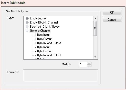
IO-Link devices from Beckhoff are automatically added with the required parameters.
To use IO-Link devices from other manufacturers, use a "Generic Channel" and select the process data size. For the process data size of the IO-Link device, refer to the documentation or contact the manufacturer.
Configuration of the IO-Link device
The minimum settings required for operating an IO-Link device are:
IO-Link version: Generally 1.1; enter 11
Frame capability: Generally 1
Min. cycle time: Generally 2.3 ms, i.e. 23
Process data in / Out length: Variable (number in bits), for a size of 2 bytes input enter 16 for "Process data in length".
If the IO-Link slave has more than 16 bits, the high bit is set (BIT 7 TRUE), then the data length is specified in bytes + 1, example 4 bytes of process data, a 0x83 (131 dec) must be specified, 0x8x then stands for counting bytes and the length is then 3 (=4 bytes). A maximum of 32 bytes is then possible here.
Master control: set to IO-Link
All other settings are optional.
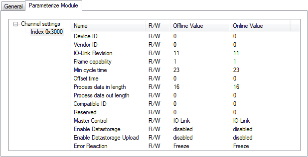 Fig.4: Configuration of the IO-Link device
Read and write parameters
Each IO-Link device has parameters that can be read or written. The ER9320-0022 does not support this function. No parameters can be read or written. The communication of the ER9320-0022 with an IO-Link device is limited to the process data.
To access parameters of the IO-Link devices, use a Beckhoff controller (e.g. CX8093). Here you can read the IODD file (IO-Link device description) and read or write the sensor data via the PLC.