Information objects
90n0 IO Info data Ch.x
- 9000: IO Info data Ch.1
- 9010: IO Info data Ch.2
- 9020: IO Info data Ch.3
- 9030: IO Info data Ch.4
Subindex (hex) | Name | Meaning | Data Type | Flags | Default |
|---|---|---|---|---|---|
0 | IO Info data Ch.x |
| USINT | RO | 0x27 (39dec) |
04 | Device ID | The device ID is used for validating the IO-Link device. | UDINT | RO | - |
05 | Vendor ID | The vendor ID is used for validating the manufacturer of the IO-Link device. | UDINT | RO | - |
20 | IO-Link Revision | ID of the specification version based on which the IO-Link device communicates. Bit 0-3: MinorRev | USINT | RO | - |
21 | Frame capability | The Frame Capability indicates certain functionalities of the IO-Link device (e.g. SPDU supported). Bit 0: SPDU | USINT | RO | - |
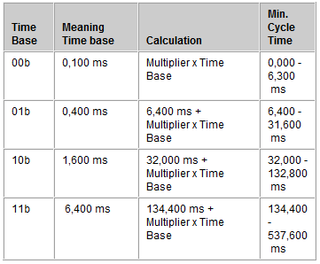
22 | Min cycle time | The cycle time refers to the communication between the IO-Link master and the IO-Link device. Bit 6 and 7: Time Base
| USINT | RO | - |
23 | Offset time | reserved | USINT | RO | - |
24 | Process data in length | These parameters are transferred in the IO-Link format for "Process data in length". Bit 7: Bit 6: Bit 0 to 4: | USINT | RO | - |
Subindex (hex) | Name | Meaning | Data Type | Flags | Default |
|---|---|---|---|---|---|
25 | Process data out length | These parameters are transferred in the IO-Link format for "Process data out length". Bit 7: Bit 6: Bit 0 to 4: | USINT | RO | - |
26 | Reserved | reserved | UINT | RO | - |
27 | Reserved2 | reserved | UINT | RO | - |
A0n0 IO Diag data Ch.x
- A000: IO Info data Ch.1
- A010: IO Info data Ch.2
- A020: IO Info data Ch.3
- A030: IO Info data Ch.4
Index (hex) | Name | Meaning | Data Type | Flags | Default |
|---|---|---|---|---|---|
A000:0 | IO Diag data Ch.x |
| USINT | RO | 0x2 (2dec) |
A000:01 | IO-Link State | The value of the IO-Link state corresponds to a state from the IO-Link master state machine 0: INACTIVE 7: PREOPERATE | USINT | RO | - |
A000:02 | Lost Frames | This parameter counts the number of lost IO-Link telegrams. This value is deleted whenever IO-Link starts up, otherwise it is incremented continuously. | USINT | RO | - |
F100 Diagnosis Status data
See chapter Status of the IO-Link ports.
Index (hex) | Name | Meaning | Data Type | Flags | Default |
|---|---|---|---|---|---|
F100:0 | Diagnosis Status data |
| USINT | RO | 0x4 (4dec) |
F100:01 | State Ch1 | IO-Link Status byte Ch. 1 | USINT | RO | - |
F100:02 | State Ch2 | IO-Link Status byte Ch. 2 | USINT | RO | - |
F100:03 | State Ch3 | IO-Link Status byte Ch. 3 | USINT | RO | - |
F100:04 | State Ch4 | IO-Link Status byte Ch. 4 | USINT | RO | - |
F101 DeviceState Status data
Index (hex) | Name | Meaning | Data Type | Flags | Default |
|---|---|---|---|---|---|
F101:0 | DeviceState Status data |
| USINT | RO | 0x10 (16dec) |
F101:0D | Device Diag | - | BOOL | RO | - |
F101:10 | Device State | - | BOOL | RO | - |
F900 Info data
Index (hex) | Name | Meaning | Data Type | Flags | Default |
|---|---|---|---|---|---|
F900:0 | Info data |
| USINT | RO | 0x1 (1dec) |
F900:01 | IO-Link Version | - | USINT | RO | - |