Configuration objects
800n IO Settings Ch.x
- 8000: IO Settings Ch.1
- 8001: IO Settings Ch.2
- 8002: IO Settings Ch.3
- …
- 8007: IO Settings Ch.8
 | Recommendation: Configuration via configuration tool TwinCAT includes a graphical configuration tool for IO-Link masters and IO-Link devices. With this tool the configuration is easier and clearer than via the CoE parameters. See chapter Configuration of the IO link master. |
Subindex (hex) | Name | Meaning | Data Type | Flags | Default |
|---|---|---|---|---|---|
0 | IO Settings Ch.x |
| USINT | RO | 0x28 (40dec) |
04 | Device ID | The Device ID is used for validating the IO-Link device. | UDINT | RW | - |
05 | Vendor ID | The Vendor ID is used for validating the vendor of the IO-Link device. | UDINT | RW | - |
20 | IO-Link Revision | The version of the IO-Link specification according to which the IO-Link device communicates. Bit 0-3: MinorRev | USINT | RW | - |
21 | Frame capability | Frame capability indicates certain functionalities of the IO-Link device (e.g. SPDU supported). Bit 0: SPDU | USINT | RW | - |
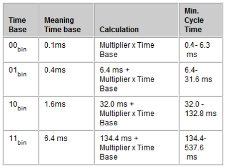
22 | Min cycle time | The cycle time at which the IO-Link master should communicate with the IO-Link device. This value is transferred in the IO-Link format for Min Cycle Time. Bit 6 and 7: Time Base 0x00: The IO-Link master automatically uses the smallest possible update time of the IO-Link device.
| USINT | RW | - |
23 | Offset time | reserved | USINT | RW | - |
Subindex (hex) | Name | Meaning | Data Type | Flags | Default |
|---|---|---|---|---|---|
24 | Process data in length | These parameters are transferred in the IO-Link format for "Process data in length". Bit 7: Bit 6: Bit 0 to 4: | USINT | RW | - |
25 | Process data out length | These parameters are transferred in the IO-Link format for "Process data out length". Bit 7: Bit 6: Bit 0 to 4: | USINT | RW | - |
26 | Compatible ID | reserved | UINT | RW | - |
27 | Reserved | reserved | UINT | RW | - |
28 | Master Control | Possible values:
| UINT | RW | - |
F820 ADS Server Settings
Index (hex) | Name | Meaning | Data Type | Flags | Default |
|---|---|---|---|---|---|
F820:0 | ADS Server Settings |
| USINT | RO | 0x2 (2dec) |
F820:01 | Net ID | NetId and port to which the DiagHistory messages can be sent via emergency | ARRAY [0..5] OF BYTE | RW | - |
F820:02 | Port | UINT | RW | - |