Process image

In the following sections, the letter n serves as a placeholder for the channel number.

Screenshots showing process data objects of channel 1 are used as examples for both channels. The process data objects of channel 1 and channel 2 have the same content structure.
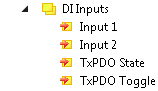
DI Inputs

Process image 1:

Process image 2: Input 1
Digital input, channel 1

Process image 3: Input 2
Digital input, channel 2

Process image 4: TxPDO State
If this bit is TRUE:

  • The digital inputs could not be read correctly due to an error.
  • The current values of the variables “Input 1” and “Input 2” are invalid.

Process image 5: TxPDO Toggle
This bit is inverted each time an input data update occurs.

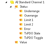
AI Standard Channel n

Process image 6:

Process image 7: State

  • "Underrange"
    The current measured value is smaller than the smallest value of the nominal measuring range. See Measuring range monitoring.
  • "Overrange"
    The current measured value is greater than the full scale value. See Measuring range monitoring.
  • "Limit 1"
    Status bit of the Limit value monitoring
  • "Limit 2"
    Status bit of the Limit value monitoring
  • "Error"
    Status bit of Measuring range monitoring.
    This bit is coupled with the LED "R/E": if the bit is TRUE, the LED lights up red.
  • "TxPDO State"
    If this bit is TRUE:
    • The measured value could not be read correctly due to an error.
    • The current value of the variable "Value" is invalid.
  • "TxPDO Toggle"
    This bit is inverted each time the measured value is updated.

Process image 8: Value
The current measured value. Data type: INT

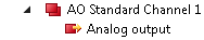
AO Standard Channel n
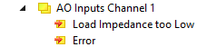
Process image 9:

Process image 10: Analog output
Analog output. Data type: INT

AO Inputs Channel n

EPP4304-1002:

Process image 11:


This process data object is disabled in the factory settings. Activation and evaluation are described in the chapter Diagnosis.

EPP4314-1002:

Process image 12: