Sample program 9 (measuring range combination)
Note on this chapter: The use of EL3751/ELM3xxx terminals also applies accordingly to EPP35xx.
In some applications it can be of interest to measure a value with very fine resolution in a small range, but still detect high deflections. If it is an AC/DC signal that has to be resolved around 0, the following approach can be used: Two inputs of an ELM terminal are electrically connected to simultaneously measure the signal, but with different measuring ranges.
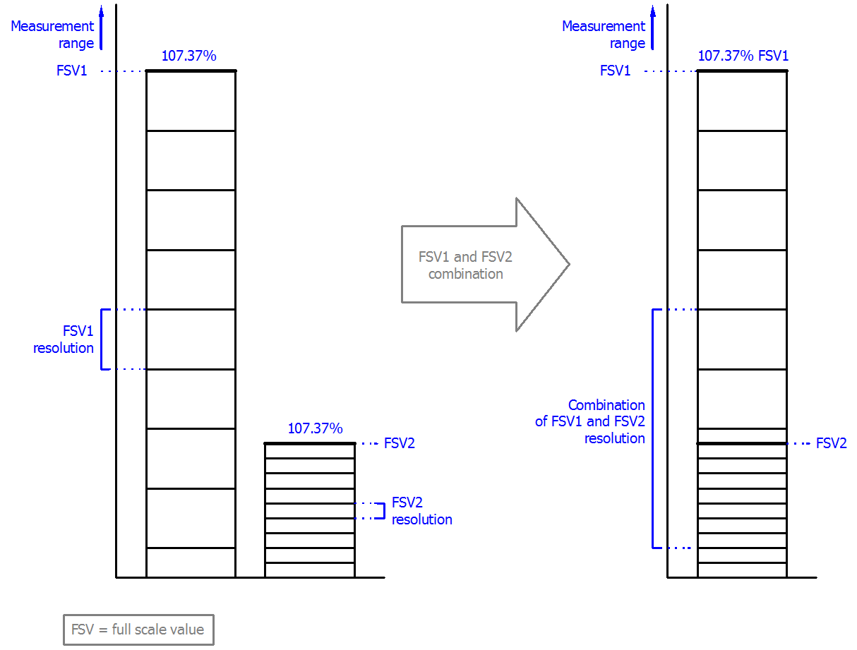 Fig.34: Principle of combining two measuring channels with FSV1 and FSV2
The dynamic range of a typical 24-bit voltage or current measurement range with the absolute PDO end value of 223 (bit 24 is sign) is 20 · log(223) ≈ 138.5 dB (without consideration of measurement uncertainties). Now it is possible to connect two (or more) inputs of a measuring system of the same measurement type with different measurement range end values (FSV1, FSV2, FSVn) in parallel to increase the dynamic range. The measured input value is then logged with two measuring ranges FSV1 and FSV2 through combination of two inputs. If FSV2 < FSV1 is selected and thus a lower resolution of FSV2 than FSV1, the low resolution of FSV2 is available if the magnitude of the measured input value is <= FSV2, and the measured input value can also be acquired for the larger range up to <= FSV1.
Note: The general definition is used to calculate the dynamic range:
Dynamic range = largest measured value / smallest unit
For output in dB accordingly with 20 · log(FSV / ResolutionFSV). In this sample, using a combination of FSV1 and FSV2, the calculation is as follows:
Dynamic range = 20 · log(FSV1 / Resolution FSV2 ).
The following sample program is based on a parallel connection of two input channels of the ELM3602-0002:
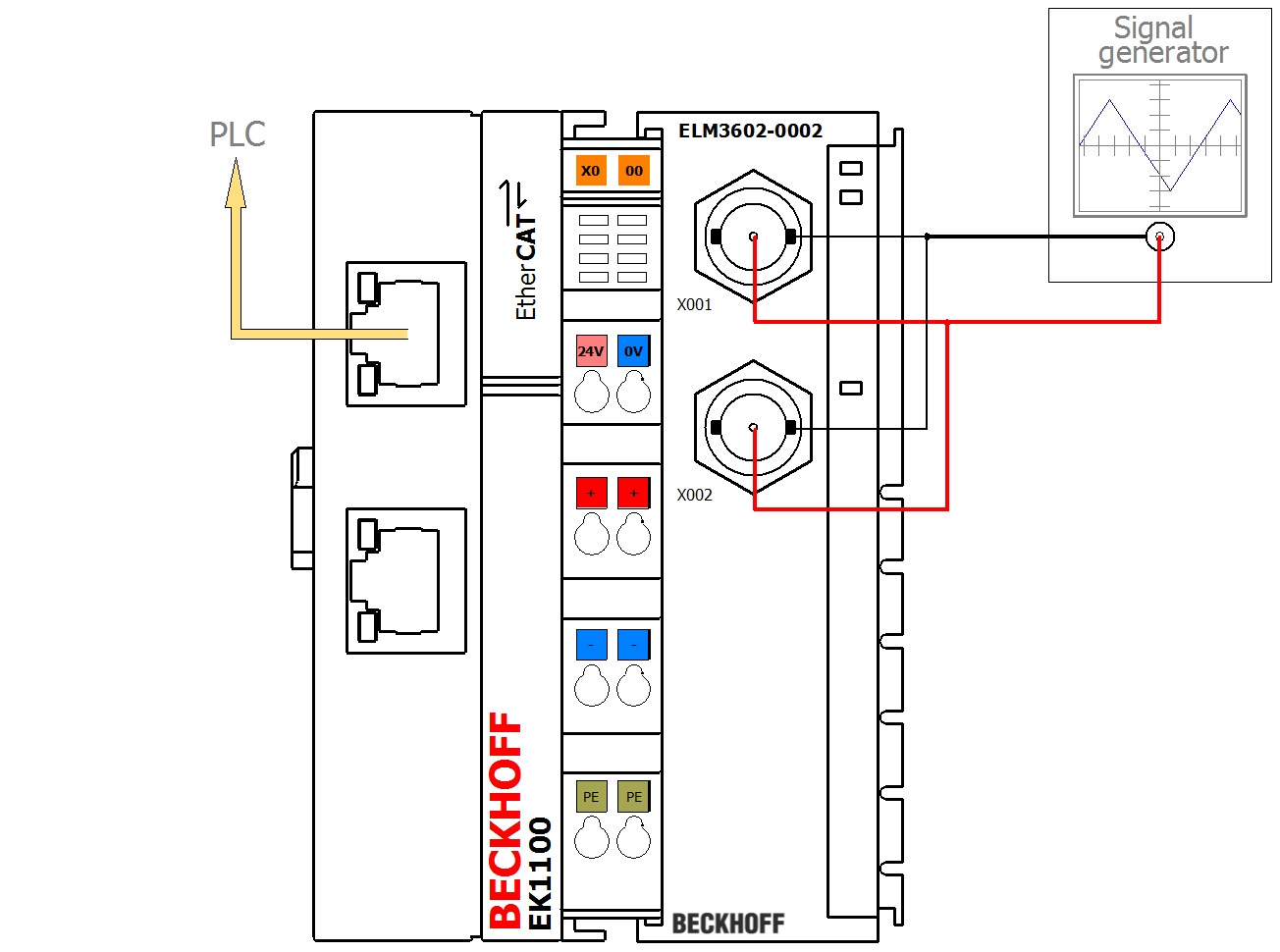 Fig.35: Possible structure for the "Measurement range combination" sample program
Program description / function
The FSV1 of channel 1 is selected as ± 5 V, the FSV2 of channel 2 as ±80 mV. The program takes the measured input value from either channel 1 or channel 2 for a common variable depending on the magnitude of the unsigned amount of the measured input value: Initially, the limit value of 107% of the FSV2 (8388607) is verified.
In the CoE object directory, the following settings should be applied in the in the PAI settings objects, according to the variables nFSV_HI and nFSV_LO:
0x8000:01 → ±5 V
0x8010:01→ ±80 mV
Scaling for both channels: "Extended Range"; no filters active (corresponds to the default setting of the terminal).
Variables declaration:
PROGRAM MAIN

VAR CONSTANT

   nFSV_PDO              :  REAL := 7812500;

   nMAX_PDO              :  REAL := 8388607;


   nEXT_F                : REAL := nMAX_PDO/nFSV_PDO;

   nFSV_HI               :  REAL := 5;    // V

   nFSV_LO               :  REAL := 0.08; // V

   nStep_HI              :  REAL := nFSV_HI/nFSV_PDO;

   nStep_LO              :  REAL := nFSV_LO/nFSV_PDO;

END_VAR

VAR

   nSamplesIn1    AT%I*  :  DINT;

   nSamplesIn2    AT%I*  :  DINT;

   nValueCombi           :  LINT;

   nValueCombi_LREAL     :  LREAL;

   nKF                   :  REAL := nFSV_HI/nFSV_LO;

   nLimit                :  REAL := nMAX_PDO;

   nPDO1_REAL            :  LREAL;

   nPDO2_REAL            :  LREAL;

// Voltage values:

   nVoltage1             :  LREAL;

   nVoltage2             :  LREAL;

   nVoltageComb          :  LREAL;

END_VAR
Program code:
nPDO1_REAL := DINT_TO_LREAL(nSamplesIn1);

nPDO2_REAL := DINT_TO_LREAL(nSamplesIn2);

IF ABS(nPDO2_REAL) >= nLimit THEN

   nValueCombi_LREAL := nPDO1_REAL*nKF;

ELSE

   nValueCombi_LREAL := nPDO2_REAL;

END_IF

nValueCombi := LREAL_TO_LINT(nValueCombi_LREAL);

nVoltage1 := nPDO1_REAL * nFSV_HI/nFSV_PDO;

nVoltage2 := nPDO2_REAL * nFSV_LO/nFSV_PDO;

nVoltageComb := nValueCombi_LREAL * nFSV_LO/nFSV_PDO;
An application of this sample with a ±5 V FSV1 and a ±80 mV FSV2 and an input signal of ±5.68 V shows the voltage curve at input 1, input 2 and both combined inputs as a continuous range in the lowest recording. In the recording of input 2 the range of +/- overflow is marked (negative/ positive clipping):
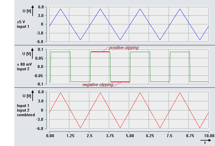 Fig.36: Combination of two channels of the ELM3602-0002 with ±5 V and ±80 mV measuring range
With an applied delta voltage of approx. 86 mV ±5 mV, the transition range is indicated by the voltage characteristic of input 2 (values < 0 V):
 Fig.37: Combination of two channels of the ELM3602-0002: Supply of a delta voltage in the positive transition range
The following applies to the (preset) extended range of both channels (without taking any measurement uncertainties into account):
If the dynamic range for the ± 5 V measuring range is approx. 20 · log (5.368 / 6.4E-7) ≈ 138.47 dB, the combination of two channels of the terminal can be used to increase the dynamic range to approx. 20 × log (5.368 / 1.024E-8) ≈ 174.39 dB (with the limitation of a coarser resolution in the range of approx. ± 85.9 mV to ± 5.37 V).
Please note that under these conditions the terminal always displays errors via the error LED and the error bit and outputs error messages to the TwinCAT environment due to regularly occurring overflow of a measuring channel.