Sample program 7 (general decimation in the PLC)
The EPP3504‑0023/ ERP3504‑0022 can only decimate their basic sampling rate fmax by integer multiples, see chapter "Decimation". To realize any other sampling rates (ftarget < fmax) for a channel, you can proceed as follows, for example:
- Operate the box module /channel at the maximum sampling rate and transfer the data to the controller (PLC) via EtherCAT/oversampling
- In the PLC/ C++, on the time axis, convert to the desired sampling rate, e.g., by linear interpolation based on the timestamp for each input value (sample). Since the EPP3504‑0023/ ERP3504‑0022 units provide time-equidistant samples based on distributed clocks, this is easily possible.
For example, a sinusoidal signal decimated with 50/44.1 = 1/0.882 can be represented as follows: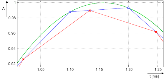
- Green: corresponds to original analog signal (input), approx. 432 Hz
- Blue (O): corresponds to sampling of the EPP3504‑0023/ ERP3504‑0022 with fmax of 10,000 sps; a sampling interval of 100 µs
- Red (X): corresponds to signal converted by PLC to 8820 sps (factor 0.882) and thus a time interval of approx. 113.37.. µs
- Note: The term "decimation" is applied both to the calculation in the box module (see chapter "Decimation") and to the conversion in the PLC program. The following refers to the conversion in the PLC.
- Since the time interval of the desired sampling after decimation in the PLC is usually no longer an integer (finite) number, value/time pairs are used for representation in the PLC/Scope, i.e., an X time value is assigned to each Y value. Such value/time pairs can easily be displayed with TwinCAT ScopeView in XY mode. See also infosys.beckhoff.com:
TwinCAT3 → TExxxx | TC3 Engineering → TE13xx | TC3 ScopeView → Configuration → XY‑Graph - The conversion also has consequences for further processing in PLC/C/ADS:
- A PLC/EtherCAT/TwinCAT system tends to be set up such that a constant number of samples is processed per cycle. Usually this is now no longer the case: a different number of samples has to be processed from cycle to cycle (specified by the program variable nResultNoOfSamples).
- While a time stamp per signal value has so far remained relatively insignificant, the method of conversion of the decimation process used here, however, means that the respective timestamp per signal value must be taken into account in an elementary manner.
- The non-constant number of samples is not visible in the TwinCAT XY Scope because some values are sporadically drawn twice, and this should be taken into account; it may be advisable to use an intermediate buffer for further processing.
- For orientation of the currently valid number of samples per task cycle, the program provides the variable nResultNoOfSamples. It indicates which values in the array variable contain valid values in a task cycle (indicates the field number - 1).
The following sample program, which also contains the XY representation in the TwinCAT Scope, serves as a guide. Due to the above-mentioned problem relating to the non-constant number of valid samples, the program returns the array pair aVarDecResult_TS and aVarDecResult for the Scope with the same number of elements as for the input value aSamples_1 (value = nOVS). If there are fewer values in a task run, the last value is simply entered repeatedly (similar to "sample & hold"). The ScopeView was configured as follows for the recording:
Property | Value | |
|---|---|---|
ScopeNodeProperties | ViewDetauilLevel | ExtendedXYOnly |
Record time | 00:00:00:05 | |
ChartXYNodeProperties | Default Display Width | 0,00:00:00,050:000 |
Max Data Points | 200000 | |
XYChannelNodeProperties | Marks | On |
Mark Size | 5 | |
Mark Color | (other than line color) | |
For an illustrative representation, the ScopeView recording was started first and then the program, which limits the decimated values to one second:
IF nOVS_CycleCount = 1000000000 THEN ; bEnable := FALSE;// Stop after 1s just for recording ELSE...This line can, of course, be commented out for further adjustments:
//bEnable := FALSE;// Stop after 1s just for recording
Notes:
- the target sampling rate ftarget should be close to the sample rate fmax, so that it is possible to evaluate a time interval between two decimated values. The desired decimation may require further parameters such as task cycle time, oversampling factor etc. to be adjusted both in the configuration and as variable initialization in the sample program (see figure "Process of variable decimation of the sample program", which illustrates the functionality of the program code).
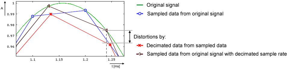
- Basically, the conversion process in this sample program causes distortions in the result in relation to the original signal shape when decimating with fractional rational factors (see signal curve). In concrete terms, deviations from the original signal curve only occur in those sections where the time derivative value (the slope) is not constant. For example, input values of a sine signal in the non-linear sections are distorted by the interpolation performed in the program:
 In the frequency spectrum, for example by a calculation with 20 Hz sinus signal, sampled with 500 sps and decimated to 441 sps, this is illustrated as follows:
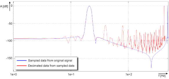
- If no low-pass filtering corresponding to ftarget is performed on the data stream, aliasing effects will occur! It is therefore advisable to perform low-pass filtering in the PLC, e.g. with the TC3 Controller Toolbox or the TC3 Filter Library, before the conversion/decimation is performed. Suitable filters can easily be created with the TE1310 FilterDesigner. For more information, see www.beckhoff.com:
Automation → TwinCAT 3 → TE1xxx | TC3 Engineering → TE1310 | TC3 Filter Designer
Alternatively, the filters available in the EPP3504‑0023/ ERP3504‑0022 can, of course, be set to the suitable low-pass frequency; the TwinCAT Filter Designer is also helpful for this. - Entries of decimation factors within the program (nDecimationValue) should have a value > 1. The program code supports down sampling only.
E.g.: If a terminal such as ELM3602-0002 (2-channel IEPE evaluation) provides a data stream with oversampling of 50 ksps at 100 µs cycle time, this sample code can decimate to 44.1 ksps. In the sample program, the cycle ticks in the task configuration should be changed from 5 to 1 and the corresponding program variable nTaskCycle_ns from 500000 to 100000. See the following image section of ScopeView XY:
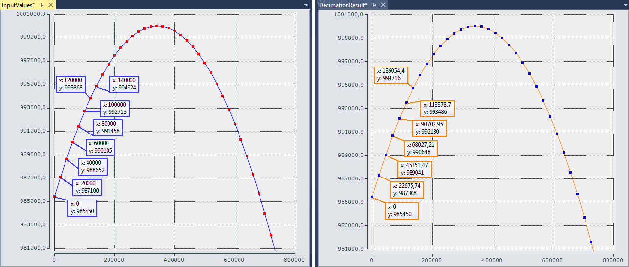 Fig.33: Decimation from 20 µs (left) to 22.675.. µs (right) with ELM3602
The decimation factor is given by entering the value "50/44.1" for nDecimationValue in the sample. If this sample is used for the EL3751 with 500 µs cycle time and 5x oversampling, the sampling interval of 100 µs, which originates from the EL3751, is converted to approx. 113.378.. µs. This sample is designed accordingly.
The decimation in the program is freely selectable and must be configured with an oversampling factor and a task cycle time. The variable nOVS must contain the same oversampling factor as set in the process data configuration.
Download sample program 7:
- Configuration: IPC + EK1100 + EL3751 + EL9011:
Program link - Configuration: IPC + EK1100 + ELM3602‑0002 + EL9011:
Program link
Note: When using an EtherCAT box like the EPP35xx, the EtherCAT coupler EK1100 is omitted.
General information
The time at which the EtherCAT frames are passed to the box module is subject to fluctuations, referred to as EtherCAT frame jitter. If these fluctuations are large in relation to the cycle time, it is possible that data is fetched late from the box module, and dropouts/duplications may occur in the scope display. Such effects can be diagnosed with TwinCAT EtherCAT diagnostics. In the sample program for the ELM3602, the variable nEqualTimeStampsCnt is available for this kind of verification. The variable is incremented if such a failure occurs. It can be remedied by changing the DC ShiftTime of the box module; see the EtherCAT system documentation.
Declaration part:
// THIS CODE IS ONLY AN EXAMPLE - YOU HAVE TO CHECK APTITUDE FOR YOUR APPLICATION

PROGRAM MAIN

VAR CONSTANT

    // User decimation factor e.g. 50 to 44.1 kSps:

    nDecimationValue       :LREAL := 50/44.1; // 50/20;

    nOVS                   :BYTE := 5;        // Oversampling factor

    nTaskCycle_ns          :UDINT := 500000;  // PlcTask configured cycle time in ns


    nOVSTimeInterval_ns    :UDINT := LREAL_TO_UDINT(nTaskCycle_ns/nOVS); // OVS interval

    nDecTimeInterval_ns    :LREAL := nDecimationValue * nOVSTimeInterval_ns; // Decimation interval

END_VAR

VAR

   aSamples_1 AT%I*        :ARRAY[0..nOVS-1] OF DINT;     // Link to the terminal PDO

   aOVS_SampleSets         :ARRAY[0..(2*nOVS)-1] OF DINT; // 2 OVS sample sets


   nVarDecResult           :DINT;  // The calculated interpolated value

   tVarDecResult           :LREAL; // Decimation timestamp

   aVarDecResult           :ARRAY[0..nOVS-1] OF DINT; // Decimation result values

   aVarDecResult_TS        :ARRAY[0..nOVS-1] OF LREAL; // Decimation result timestamps


   nResultNoOfSamples      :BYTE; // This is for the user for further processing


   nDivVar                 :INT;  // Value for selection of the target input element

   tDecVar_InTaskCycle     :LREAL:=0; // Time span for all decimation timestamps within a task cycle

   i                       :BYTE:=0; // Common loop counter

   nDX                     :LREAL; // X-Difference: target input element to decimation element

   nDY                     :DINT;  // Y-Difference: two values for interpolation

   sVal                    :LREAL; // Slope for calculation of new value

   bEnable                 :BOOL:=FALSE; // Start/Stop conversion to decimation values

   nOVS_CycleCount         :ULINT := 0;  // Time value for every OVS sample

   // Values for testing

   bTEST_VALUES_ENABLED    :BOOL := FALSE; // No input value needed, if TRUE

   nPhi                    :LREAL := 1.4; // Start angle for sinus simulation

   // For visualization only:

   aOVS_Samples            :ARRAY[0..nOVS-1] OF DINT;  // 2 OVS sample sets (value)

   aOVS_Samples_TS         :ARRAY[0..nOVS-1] OF ULINT; // 2 OVS sample sets (timestamp)

END_VAR
Execution part:
// 500 µs Task

FOR i:= 0 TO nOVS-1 DO

   // Shift OVS set to left and update on right:

   aOVS_SampleSets[i] := aOVS_SampleSets[i+nOVS];   // Transfer "samples set" to the left side

   IF bTEST_VALUES_ENABLED THEN

      // Simulate values:

      aOVS_SampleSets[i+nOVS] := LREAL_TO_DINT(1000000 * SIN(nPhi));

      nPhi := nPhi + 0.01;//0.003141592653;

   ELSE

      // Fill current new samples set on right:

      aOVS_SampleSets[i+nOVS] := aSamples_1[i];

   END_IF

END_FOR

IF bEnable THEN

   nResultNoOfSamples := 0; // Use for further processing


   FOR i := 0 TO nOVS-1 DO

      nDivVar := TRUNC_INT(tDecVar_InTaskCycle/nOVSTimeInterval_ns);

      // Check, if new value is in grid

      IF (nDivVar = i) THEN

         nResultNoOfSamples := nResultNoOfSamples + 1;


         // Calc slope by the left and right element values (dy/dx):

         nDY := aOVS_SampleSets[i+1] - aOVS_SampleSets[i];

         sVal := DINT_TO_LREAL(nDY)/nOVSTimeInterval_ns;

         // Get the time (difference) from the left side element start to the desired time point:

         nDX := tDecVar_InTaskCycle

                 - TRUNC_INT(tDecVar_InTaskCycle/nOVSTimeInterval_ns)

                 * UDINT_TO_LREAL(nOVSTimeInterval_ns);

         // Calc timestamp

         tVarDecResult := nDX + ULINT_TO_LREAL(nOVS_CycleCount);

         // Calc new value:

         nVarDecResult :=

                  LREAL_TO_DINT(DINT_TO_LREAL(aOVS_SampleSets[i]) + sVal * nDX);


         // next decimation time step

         tDecVar_InTaskCycle := tDecVar_InTaskCycle + nDecTimeInterval_ns;

         tDecVar_InTaskCycle := tDecVar_InTaskCycle

                 - INT_TO_UDINT(TRUNC_INT(tDecVar_InTaskCycle/nTaskCycle_ns))

                 * nTaskCycle_ns;

      END_IF

      // Fill timestamp and new value allocated to the field element of its timestamp

      aVarDecResult_TS[i] := tVarDecResult;

      aVarDecResult[i] := nVarDecResult;

      // For visualization of the original input:

      aOVS_Samples[i] := aOVS_SampleSets[i];

      aOVS_Samples_TS[i] := nOVS_CycleCount;

      // Count the task cycle timestamp

      nOVS_CycleCount := nOVS_CycleCount + nOVSTimeInterval_ns;

   END_FOR

END_IF

IF nOVS_CycleCount = 1000000000 THEN

   bEnable := FALSE;// Stop after 1s just for recording

   IF NOT bEnable THEN

      bEnable := TRUE; // OVS‑Samples transferred complete into both array sets

   END_IF

END_IF