Sample program 6 (interlacing of measured values)
Program description / function
Note on this chapter: The use of EL3751/ELM3xxx terminals also applies accordingly to EPP35xx.
In some use cases a particularly fine temporal resolution of the signal is desired, e.g. so that many measuring points are available for an FFT. Two ways to do this are shown below:
- Use of an analog input terminal with the correspondingly high sampling rate, e.g. 20 ksps.
- Use of two analog input terminals with half the sampling rate, i.e. 10 ksps, and so-called interlacing of measured values; the result is likewise a 20 ksps sampling of the signal.
The second way is described in this sample: Use of two EL3751 EtherCAT Terminals, each with a maximum sampling rate of 10 kSps (and thus a conversion time of 100 µs in this case, cf. Further documentation for I/O components with analog in and outputs, chapter “Temporal aspects of analog/digital or digital/analog conversion”). Due to their parallel connection, both terminals are fed the same signal simultaneously and are configured by Distributed Clocks in such a way that they sample not at the same time, but offset by half the conversion time (in this case: 50 µs). If the two measured data streams are now combined alternately in the controller, i.e. "interlaced", the result is a net measured data stream of 20 ksps.
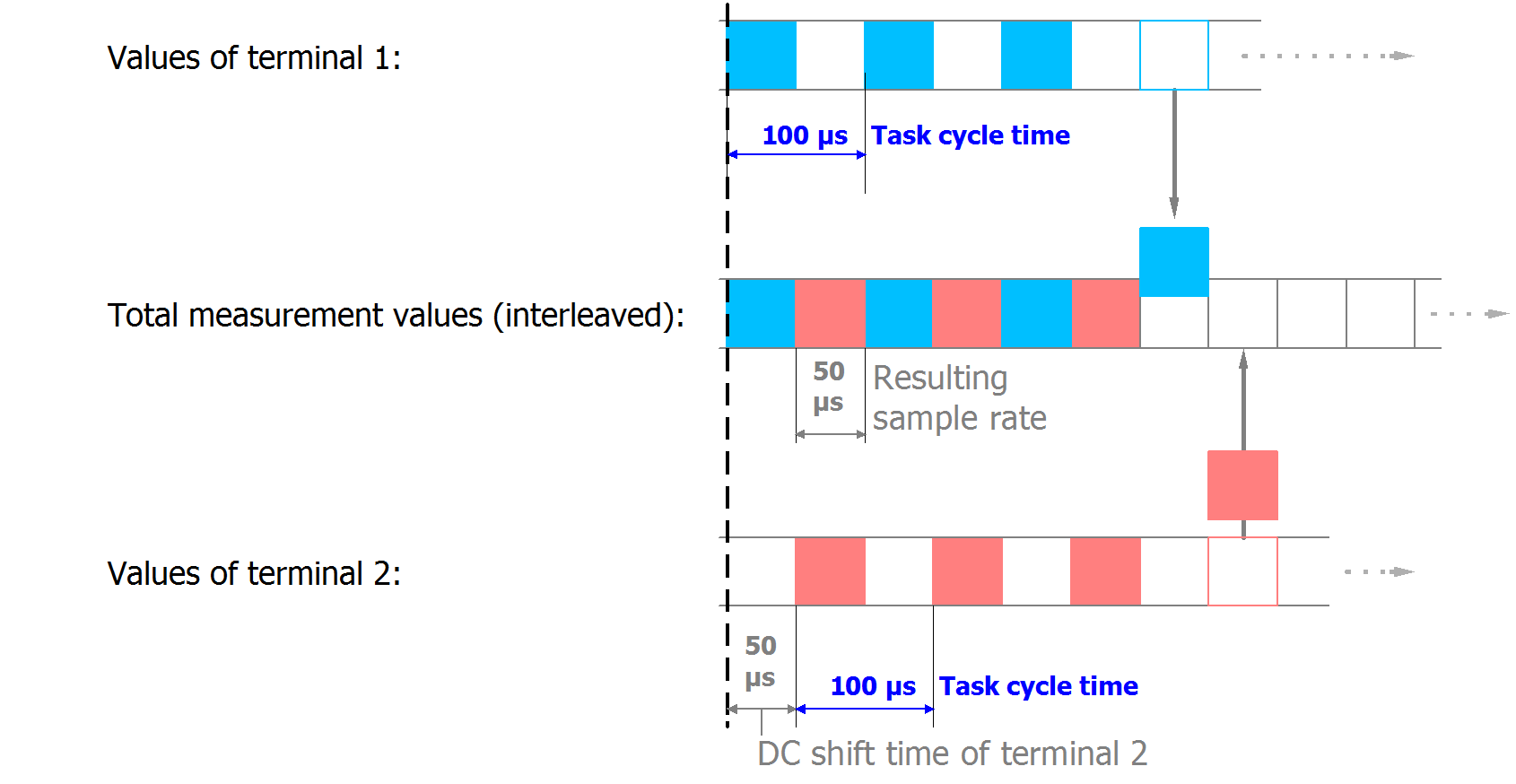 Fig.28: Process of interlacing the input data
The following configuration is used for this purpose:
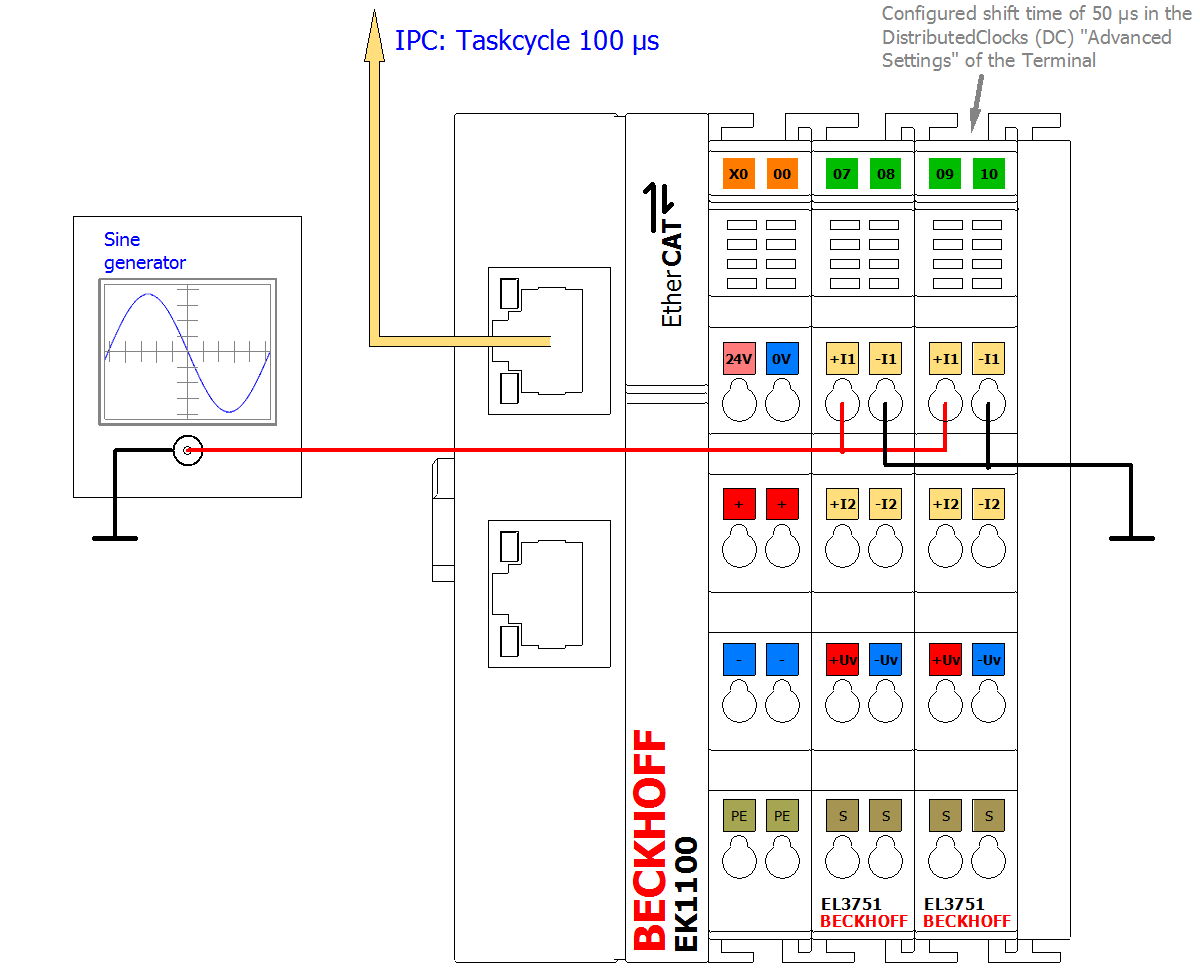 Fig.29: Configuration and setup for sample program 6: Doubling of the sample rate with 2 x EL3751
The sample is also available with corresponding adaptations for other EL3xxx/ELM3xxx terminals or box modules. There may then be different oversampling factors, shift times, etc. The optionally existing task with 50 µs in sample 6a may then also not be usable.
So that the input values can be successively combined to form a total value, a corresponding shift time is necessary for each channel/terminal; in this sample 50 µs for the second terminal. This is set in the "Advanced settings" for Distributed Clocks ("DC" tab) for the second terminal:
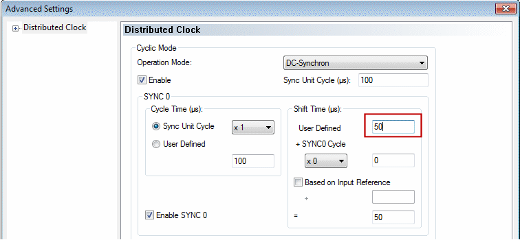 Fig.30: Setting the DC shift time for terminal 2
Some notes and restrictions
- This principle can be implemented with two (as described above) or more terminals; the limit is the shift time fineness of 1 µs.
- The terminals used must support Distributed Clocks. Oversampling is helpful, but not necessary. The sampling methods simultaneous vs. multiplex must be considered; see corresponding documentation with the question: "when the channels sample their values in relation to Distributed Clocks".
- Although this approach doubles the sampling rate of the signal under observation, the frequency response and attenuation specified in the technical data for the terminal still apply! It is therefore not possible to read signals that are twice as fast with twice the sampling rate. Sample: the EL3751 with a sampling rate of 10 ksps can meaningfully (alias-free) read signals up to half the sampling rate = 5 kHz. This limit remains even with multiple parallel sampling! The attenuation of -3 dB at 3 kHz given as an example also applies to the interlaced sum signal.
- Only one EtherCAT terminal can be functionally time-shifted as a whole by Distributed Clocks shift time, not the individual channel of a terminal. The shift then affects all the channels of a terminal. Therefore, for the given principle, two or more terminals/box modules must always be used; the interlacing of two channels of the same terminal/box is not possible.
- The specified measurement uncertainty must be observed: the unavoidably different real measurement uncertainty and thus the amplitude difference between the two terminals or their channels used on the same signal can become visible as a noise component after interlacing. Therefore, terminals should be used for this principle that exhibit a much smaller measurement uncertainty than is necessary for the application. It is expressly recommended to carry out an explicit user calibration of at least the offset of the two electrically interconnected channels in order to minimize this effect.
- Terminals with the same HW/FW version should be used.
Sample program
This setting, like the base time and the task cycle time, is already configured in the sample program:
Download TwinCAT 3 project / sample program 6a: EL3751_example_program_6a.zip
In the following section, the simplest form of input value interlacing in Structured Text is initially shown with oversampling = 1 for each input value: each of two elements of a field variable receives a value from a terminal. The variable can be used for further processing and is shown here in the TwinCAT ScopeView. In the EL3751 the programming instructions are assigned to a 100 µs task:
Variable declaration sample program 6a
PROGRAM MAIN

VAR

   nSamples_1         AT%I*      :DINT; // EL3751 input with no added shift time

   nSamples_2         AT%I*      :DINT; // EL3751 input with -50 µs added shift time

   aCollectedResult              :ARRAY[0..1] OF DINT;

END_VAR
Execution part:
// Example program 6a:

// 100 µs task

// ============================================================

aCollectedResult[0] := nSamples_1;   // Put 1st Value of sequence into array

// Pattern: 1.1.1.1...

aCollectedResult[1] := nSamples_2;   // Put n-th Value of sequence into array (2nd here)

// Pattern: .2.2.2.2...

// ============================================================

// Result pattern: 12121212... (--> see scope view dots)
For an input signal with sine 5 kHz and 2.5 V amplitude, for example, the TwinCAT ScopeView provides the following results:
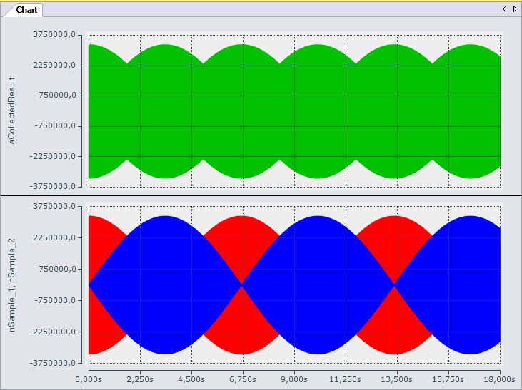 Fig.31: Oversampling 20 ksps with 2 x EL3751 with input signals (below) and result signal (top)
The upper diagram shows the total signal and the two input signals (nSample_1, nSample_2), with a time shift of 50 µs relative to each other, within 18 s in compressed form. The total input signal (nCollectedResult) indicates the interlacing of the two input signals.
The following diagram (enhanced through highlighting) shows how the input signals (nSample_1, nSample_2) contribute to the structure of the total input signal:
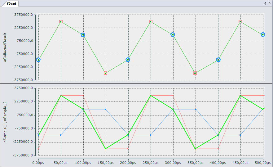 Fig.32: Oversampling 20 ksps with 2 x EL3751 shows input value 1 and input value 2 alternately for a result value
Under certain conditions, both inputs can be combined into a single variable in a correspondingly fast task. For this purpose the sample program contains an additional task with 50 µs cycle time, which is required for representing the input signals in the SopeView and contains a variable (nCollected) to which both inputs are assigned alternately:
// 50 µs task// ============================================================// Junction of the two inputsnCollected := SEL(nToggle, MAIN.nSamples_1_, MAIN.nSamples_2_);nToggle := NOT nToggle;The input variables required for the ScopeView are read in this task from the 100 µs task, so that the individual values can be represented at 50 µs intervals.
Variant with 2 x oversampling 10 = oversampling 20
If, for example, an oversampling factor of 10 is used for both input terminals, a field variable is used for the total measured value. A simple loop can be used for interlacing the input values, which reads the values sequentially into a field variable for the resulting result variable:
Variable declaration sample program 6b
PROGRAM MAIN

VAR

   aSamples_1         AT%I*      :ARRAY[0..9] OF DINT; // EL3751 input with no added shift time

   aSamples_2         AT%I*      :ARRAY[0..9] OF DINT; // EL3751 input with -50 µs added shift time

   aCollectedResult              :ARRAY[0..19] OF DINT;

// ===================================================

   nPos                          :BYTE;

END_VAR
Execution part:
// Example program 6b:

// 1 ms task

// ============================================================

FOR nPos := 0 TO 9 DO

   // Put 1st Value of sequence into array:

   aCollectedResult[2*nPos] := aSamples_1[nPos];

   // Put n-th value of sequence into array (2nd here):

   aCollectedResult[2*nPos+1] := aSamples_2[nPos];

END_FOR
Download TwinCAT 3 project / sample program 6b: EL3751_example_program_6b.zip
Sample program 6b returns the same result, except that the total input signal is only available in the form of a field variable with 20 elements.