Sample program 10 (FB for real time diagnosis)
The following function block can be used as a template for a real time diagnosis application of an EtherCAT box module analog input in TwinCAT PLC. It must be placed between the box module and the application and evaluates the diagnostic variables coming from the box module. The measurement values will be unchanged passed through.
The function block is written for the ELM3602‑0002 with oversampling = 5 and should be understood as a functional example and must be adapted if necessary to
- other terminals or box modules if necessary other value data types
- other oversampling values
It can be extended with data-processing code or further particular diagnostics or assigned to a completely different type of a box module (analog output EL4xxx, Encoder EL5xxx, ...).
The function block between the box module and the PLC can be schematically illustrated as follows:
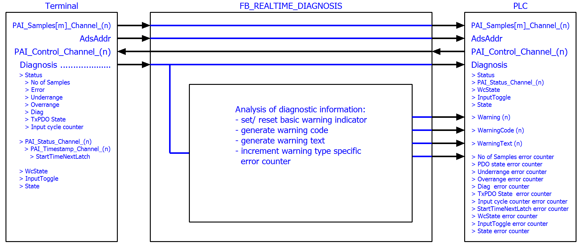 Fig.38: Function block as an example for analysis of diagnostics information of the box module
Simplified linking via structure variable
This example program takes the opportunity to describe a TwinCAT function that simplifies the linking of complex PDO structures.
This function block would have to be linked to all real time variables of the box module: inputs and outputs; here e.g., for the ELM3602:
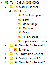
This time-consuming process can be simplified and accelerated by structuring in TwinCAT 3. Therefore, in this chapter two alternative variants in TwinCAT 3.1 are presented, as with a few clicks a structure can be defined in the PLC which corresponds to the process image of the box module.
The respective variant of the function block FB_REALTIME_DIAGNOSIS is included in the two example programs. It contains variables with an application-specific data type. This is a structure created by TwinCAT 3. Because the structure generated by TwinCAT directly maps the PDO structure of the box module, it is not necessary that a suitable structure must be elaborately created, or individual variables must be linked to individual data types. Only a link at a higher level (Status, Samples, Control, ...) is required.
This and all configurations are already included in the respective example program:
- Example program (variant A – using the “Plc” tab of the box module):
download - Example program (variant B – using of “Create SM/PDO Variables” by the advanced settings of the box module):
download
Variant A, “Plc” tab:
In general, the generation of this special PDO data type is activated via the PLC settings of the box module (tab “Plc"): there the check box "Create PLC Data Type" is set ("Copy" then transfers this character string to the clipboard):
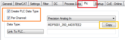 Fig.39: Creation of PDO variables (TwinCAT version >= V3.1.4024.0)
The setting "Per Channel” can be set if not for all but for one only the structure shall be created.
The address assignments for inputs (%ATI*) and outputs (%ATQ*) are already within this generated structure. Inputs and outputs are therefore summarized in this structure.
The variables declaration within the function block FB_REALTIME_DIAGNOSIS then contains:
stELM3602Special : MDP5001_350_EB559ACD;Read access is provided to the inputs of the box module via the substructure MDP5001_350_Input and write access to the outputs via the substructure MDP5001_350_Output of the structure stELM3602Special.
Variant B, “Create SM/PDO variables“:
Commonly, the generation of this specific PDO data type incl. the PDO element will be activated via the EtherCAT settings of the box module: within the advanced settings under “General”/ "Behavior" the checkbox "Create SM/PDO Variables“ in “Process Data” is to set:
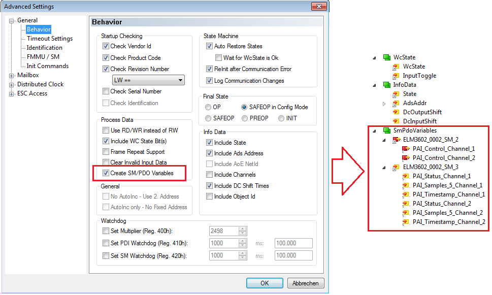 Fig.40: Creation of the SmPdoVariables (TwinCAT version >= V3.1.4022.30)
The data type is visible by selecting the object and can be copied to the clipboard there:
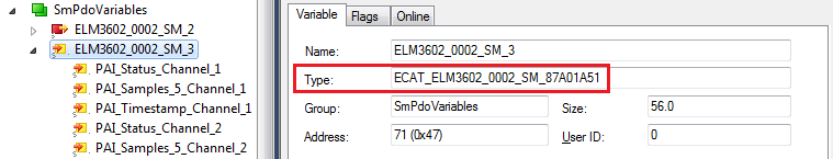 Fig.41: Seek the generated data type of SmPdoVariables
The variables declaration within the function block FB_REALTIME_DIAGNOSIS then contains:
st_SM2             AT%Q*    : ECAT_ELM3602_0002_SM_3412CB6A;

st_SM3             AT%I*    : ECAT_ELM3602_0002_SM_87A01A51;
The read access to the inputs of the application is provided via the structure st_SM3 and write access to the outputs via the structure st_SM2. These data structures corresponds to the automatically added new PDO element "SmPdoVariables".