Basics of thermocouple technology
 | General term: "device" This chapter is used in the documentation of several Beckhoff products. It is therefore written in general terms and uses the generic term "device" for the different device types such as terminal (EL/ELM/KL/ES series...), box (IP/EP/EPP series...), module (EJ/FM series…). |
Thermocouples are temperature sensors. The application areas of thermocouples are widespread due to their low cost, fast detection of temperature differences, wide temperature ranges, high temperature limits and availability in a wide range of types and sizes.
Measuring principle and configuration
Temperature measurement with a thermocouple is based on the Seebeck effect, which was discovered in the 1820s by the German physicist Thomas Johann Seebeck. The Seebeck effect, also known as thermoelectric effect, describes a charge shift in a conductive material due to a temperature gradient along the conductor. The magnitude of the charge shift depends on the magnitude of the temperature difference and the respective conductor material.
In thermocouples this charge shift is used to generate a voltage. Two different conductor materials are connected at one end. This is the measuring point at which the temperature Tm is to be determined. At the other end the conductors are not connected. This open end, where the transition to the measuring electronics is located, is the comparison point with comparison temperature or also the cold junction with cold junction temperature TCJ. A temperature difference ΔT (Tthermo) occurs between the cold junction and the measuring point, which can be measured via the voltage between the conductors at the open end (thermovoltage Uth). The voltage depends on the conductor materials used and the temperature difference. It is in the range of a few mV.
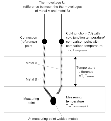
If only one material were used for a thermocouple, the charge shift in both conductors would be identical, so that no potential difference between the two conductors at the open end could be measured.
The temperature measurement with thermocouples is therefore actually a voltage measurement, based on which a temperature can be determined from the known characteristic curve. In addition, the measuring procedure is not absolute but differential, since no absolute temperature with the reference point 0 °C is determined, but the temperature difference between the measuring point and the cold junction.
For the evaluation of thermocouples, measuring electronics are required that can evaluate small voltages in the mV range with sufficiently high resolution and accuracy. Thermocouples are active sensors, which means that no sensor supply is required to measure the temperature due to the voltage will be generated by the thermocouple itself.
Thermocouple types
There are different types of thermocouples, which consist of different combinations of conductor materials. Each material combination has specific properties and is suitable for certain applications. The different types or thermocouple types are named with letters.
Due to the different material combinations, the different thermocouple types have different characteristic values. They differ in the temperature limits and the characteristic voltage/temperature curve. In order to be able to differentiate between the thermocouple types, the color codes for the sheath, the positive pole and the negative pole are defined in various standards.
The following table shows common thermocouple types with the specification of the materials used, the defined temperature ranges and the color coding.
Type (conforms to EN60584-1) | Element | Technically usable measuring range 1) | Average temperature coefficient (measuring range, recommended) | Voltage at min
| Voltage at max | Color coding (sheath - positive pole - negative pole) according to IEC 60584-3 | |
|---|---|---|---|---|---|---|---|
min | max | ||||||
A-1 | W5%Re - W20%Re | 0 °C | 2500 °C | 14.7 µV/K | 0 mV | 33.64 mV | red - white - red |
A-2 | W5%Re - W20%Re | 0 °C | 1800 °C | 15.7 µV/K | 0 mV | 27.232 mV | red - white - red |
A-3 | W5%Re - W20%Re | 0 °C | 1800 °C | 15.4 µV/K | 0 mV | 26.773 mV | red - white - red |
Au/Pt | Au-Pt | 0 °C | 1000 °C | 39.0 µV/K | 0 mV | 17.085 mV | not standardized |
B | Pt30%Rh-Pt6Rh | 200 °C | 1820 °C | 10.3 µV/K | 0.178 mV | 13.82 mV | grey - grey - white |
C 2) | W5%Re-W26%Re | 0 °C | 2320 °C | 16.8 µV/K | 0 mV | 37.107 mV | not standardized |
D | W3%Re-W25%Re | 0 °C | 2490 °C | 174.0 µV/K | 0 mV | 40.792 mV | not standardized |
E | NiCr-CuNi | -270 °C | 1000 °C | 74.2 µV/K | -9.835 mV | 76.373 mV | violet - violet - white |
G | W-W26%Re | 1000 °C | 2300 °C | 186.9 µV/K | 14.5 mV | 38.8 mV | not standardized |
J | Fe-CuNi | -210 °C | 1200 °C | 57.1 µV/K | -8.095 mV | 69.553 mV | black - black - white |
K | NiCr-Ni | -270 °C | 1372 °C | 40.3 µV/K | -6.458 mV | 54.886 mV | green - green - white |
L 3) | Fe-CuNi | -50 °C | 900 °C | 59.0 µV/K | -2.51 mV | 53.14 mV | blue - red - blue |
N | NiCrSi-NiSi | -270 °C | 1300 °C | 36.5 µV/K | -4.345 mV | 47.513 mV | pink - pink - white |
P | Pd31%Pt14%Au-Au35%Pd | 0 °C | 1395 °C | 40.2 µV/K | 0 mV | 55.257 mV | not standardized |
Pt/Pd | Pt-Pd | 0 °C | 1500 °C | 38.3 µV/K | 0 mV | 22.932 mV | not standardized |
R | Pt13%Rh-Pt | -50 °C | 1768 °C | 12.6 µV/K | -0.226 mV | 21.101 mV | orange - orange - white |
S | Pt10%Rh-Pt | -50 °C | 1768 °C | 11.1 µV/K | -0.236 mV | 18.693 mV | orange - orange - white |
T | Cu-CuNi | -270 °C | 400 °C | 48.5 µV/K | -6.258 mV | 20.872 mV | brown - brown - white |
U 3) | Cu-CuNi | -50 °C | 600 °C | 57.2 µV/K | -1.85 mV | 34.31 mV | brown - red - brown |
1) The specified measuring range refers to the maximum possible measuring range of the specified thermocouple type. The technically reasonable usable measuring range with the thermocouple measuring instruments may be limited. The possible measuring ranges of the thermocouple measuring devices are specified in the technical data in the documentation.
2) not standardized according to EN60584-1
3) according to DIN 43710
The thermocouple must be selected according to the operating conditions. Therefore, not only the uncertainty must be taken into account, but also the other properties of the different thermocouple types. For an application with small temperature fluctuations, it is advantageous to select a thermocouple type with a high thermovoltage per temperature change. In an application where the temperature to be measured is very high, it is important to observe the maximum operating temperature.
Characteristic curves of thermocouples
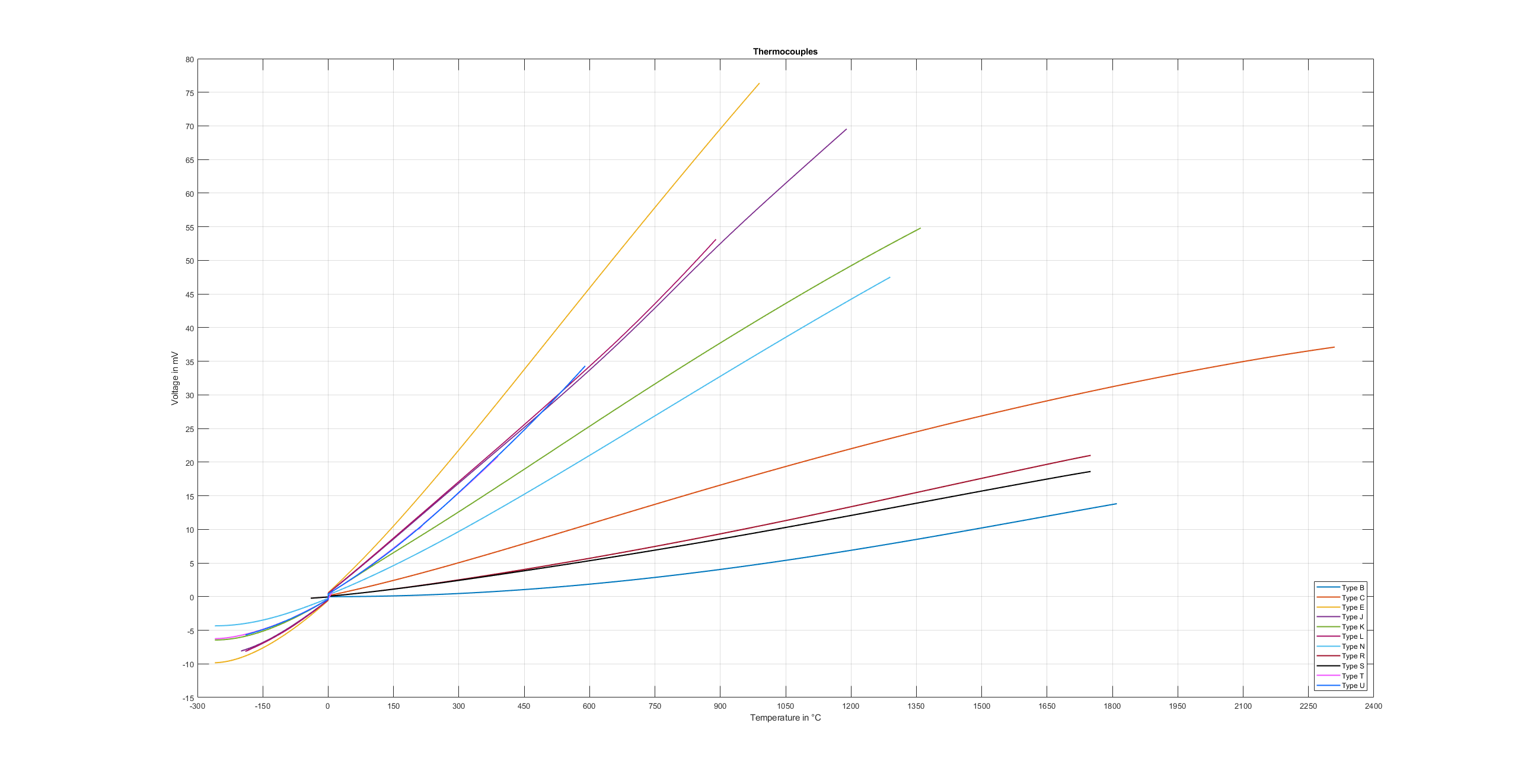
Type-specific reference tables are available for determining the temperature difference ΔT to a measured thermovoltage. A simple conversion of the voltage into a temperature with a temperature coefficient, as is often approximated in resistance thermometers, is not possible because the relationship between voltage and temperature is clearly non-linear over the entire measuring range. The changing temperature coefficient results in a non-linear characteristic voltage/temperature curve. This characteristic curve is in turn dependent on the thermocouple type, so that each type has its own non-linear characteristic voltage/temperature curve. As an example, the characteristic curves for typical thermocouple types are shown in the following diagram “Characteristic voltage/temperature curves..”. The non-linearity is particularly evident in the temperature range below 0 °C.
Thermocouples are subject to unavoidable and irreversible changes during practical application, which leads to ever-increasing measurement uncertainties over time. In other words: the measurement becomes more and more incorrect over time. These changes are also referred to as aging and depend on various influencing factors. Examples of these influences are mechanical and chemical stresses on the thermocouples. Mechanical stresses are deformations of the conductors, which change the crystal structure of the metals. This leads to incorrect thermovoltages. Chemical stresses are also changes in the crystal structure of the metals or oxidation, which change the thermal properties of the conductors, resulting in a change in the characteristic curve. This influence can be reduced by installation in gas-tight protection tubes.
Pluggable connections
Open wire ends or suitable thermocouple connectors can be used to connect thermocouples to measuring devices and evaluation electronics or to connect a thermocouple to thermo or compensating cables.
Ideally, the contacts of such a thermocouple connector are made of the material of the respective thermocouple. This results in an almost thermovoltage-free transition at the connection points. The connectors usually have fixed housing colors (normed by IEC or ANSI) depending of their type, e.g. type K is green. Labelling on the housing and different contact shapes are intended to avoid polarity reversal.
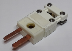
A special feature is the white connector, which is designed with normal copper contacts, almost like a simple non-thermocouple connector. This makes it universally applicable for all thermocouple types, although it has the disadvantage that it does not create a thermovoltage-free transition. Far more common than the white plug is the white "universal" socket on the measuring device. This allows any thermocouple plug to be plugged into the device. In the measuring device, the cold junction temperature must then be determined at this plug transition (see section “Measuring principle and configuration”).
Extensions and connection of thermocouples
In some cases it is useful to extend the thermocouple and thus to move the cold junction to a particular location, where the temperature can be kept constant or measured by simple means. For this purpose the thermocouple must be extended. This can be done with a thermo or compensation wire. Thermo cables are made of the same material as the thermocouple itself. Compensating cables, on the other hand, are usually made of cheaper materials with the same thermo-electric properties. Both types are therefore suitable for extending a thermocouple to a remote cold junction. The wires for thermo and compensating cables are standardized by DIN 43713.
With compensating cables, care must be taken to ensure that the material used has similar thermo-electric properties but not necessarily identical properties. The thermal properties only apply in a narrowly limited temperature range. At the transition from thermocouple to compensation wire, another thermocouple is created. This results in small thermovoltage distortions, which influence the measurement result. If the compensating cables are used outside the specified temperature range, the accuracy of the temperature measurement will be further affected and the measurement result will deteriorate.
For both thermal and compensation wires, there are two accuracy classes that indicate the limit deviations. These are defined in DIN 43722. When selecting the thermocouple extension, the resulting uncertainty should be considered and evaluated.
| Sensor circuit Changing the sensor circuit through additional elements such as selector switches or multiplexers can affect the measuring accuracy. In such switches, small local thermovoltages can be generated which distort (partly strong non-linear) the measurement. If such components cannot be avoided in the application, their influence should be carefully examined. |
| Maximum cable length to the thermocouple Without additional protective measures, the maximum cable length from the measuring device to the thermocouple is 30 m. For longer cable lengths, suitable surge protection should be provided. |
Cold junction compensation / CJC
The correction of the thermovoltage value to determine the absolute temperature value is referred to as cold junction compensation. In order to determine an absolute temperature value that is as accurate as possible, the temperature at the cold junction must either be kept constant at a known value or measured continuously during the measurement with the smallest possible uncertainty. In some applications, the cold junction may be in an ice bath (0 °C), for example. In this case the temperature determined via the thermovoltage corresponds to both the temperature difference ΔT and the absolute temperature. In many applications, however, this option cannot be implemented, so that cold junction compensation is necessary.
For thermocouple evaluation with EtherCAT and Bus Terminals in an IP20 housing, the cold junction temperature is measured at the transition from the thermocouple to the copper contacts in the conductor connection plane of the Beckhoff module/ terminal. During operation this value is continuously measured within the terminal via a sensor in order to correct the measured values. This continuous measurement can optionally be disabled in cases where external cold junction compensation is used, for example.
With the EJ plug-in modules for the PCB, the cold junction measurement is not integrated in the module. In this case, the cold junction must be measured externally. This temperature can then be transferred to the module for cold junction compensation and calculation of the absolute temperature.
For IP67 modules and for EJ plug-in modules, the cold junction is located outside the module. For cold junction compensation, Pt1000 measuring resistors must be connected externally.
For IP67 modules Beckhoff offers the ZS2000-3712 connector with integrated Pt1000 measuring resistor for this purpose.
Determination of the absolute temperature
Temperature measurement with a thermocouple is a differential temperature measurement, in which the temperature difference between the measuring point and the reference/ comparison junction, also known as cold junction, is determined. To determine the absolute temperature at the measuring point, the measured thermovoltage must therefore be corrected by the thermovoltage at the cold junction. With the corrected thermovoltage, the absolute temperature at the measuring point can then be determined from suitable tables or characteristic curves. Due to the non-linearity of the characteristic curve, it is imperative that this calculation is carried out with the voltages and not with the temperature. Otherwise, there would be a significant error in the measurement.
| Difficulties in measuring temperature with thermocouples - Linearization - Cold junction compensation |
In general, the absolute temperature is calculated using the following relationship:
Umeasuring point = Uthermo + Ucold junction
Tmeasuring point = f(Umeasuring point)
In the following section, the absolute temperature is determined as an example based on correction of the thermovoltages and the temperature. The example calculation can be used to illustrate the error resulting from incorrect calculation.
Sought: Tmeasuring point
Known: Thermocouple type K, Uthermo = 24.255 mV, Tcold junction = 22 °C
Option 1: Calculation of thermovoltages – CORRECT
The thermovoltage at the cold junction Ucold junction must be determined based on the known temperature Tcold junction from the characteristic voltage/temperature curve or table for thermocouple type K:
Ucold junction = U(22 °C) = 0.879 mV
The thermovoltage at the measuring point can then be determined with reference to 0 °C:
Umeasuring point = Uthermo + Ucold junction = 24.255 mV + 0.879 mV = 25.134 mV
The corresponding temperature value can then be determined for thermocouple type K based on the determined thermovoltage from the characteristic voltage/temperature curve or table:
Tmeasuring point = T(25.134 mV) ≈ 605.5 °C
Option 2: Temperature calculation – WRONG
In principle, the temperature difference between the cold junction and the measuring point Tthermo could be determined based on the known thermovoltage Uthermo from the characteristic voltage/temperature curve or table for thermocouple type K:
Tthermo = T(24.255 mV) = 585 °C
The temperature of the measuring point could then be determined with reference to 0 °C:
Tmeasuring point = Tthermo + Tcold junction = 585 °C + 22 °C = 607 °C
Note that there is a temperature difference of 1.5 °C between the value with the proper calculation (voltage calculation, option 1) and the value with the incorrect calculation (temperature calculation, option 2). This is a measurement deviation over 2400 ppm.
Evaluation of thermocouples with thermocouple measuring devices
Beckhoff thermocouple measuring devices can evaluate thermocouples of different types. Linearization of the characteristic curves and determination of the reference temperature takes place directly in the measuring device. The measuring device can be fully configured via the Bus Coupler or the controller. Different output formats may be selected or own scaling activated. Linearization of the characteristic curve and determination and calculation of the reference temperature (temperature at the connection contacts of the measuring device) can be disabled, so that the device can be used as a mV measuring device or with an external cold junction. In addition to the internal evaluation of the measured voltage for conversion into a temperature, the raw voltage value can be transferred from the measuring device to the control system for further processing.
Temperature measurement with thermocouples generally comprises three steps:
- Measuring the electrical voltage,
- optional: Temperature measurement of the cold junction,
- optional: software-based conversion of the voltage into a temperature value according to the set thermocouple type (K, J, …)
All three steps can take place locally in the Beckhoff measuring device. Transformation in the measuring device can be disabled if it is to take place in the higher-level control system. Depending on the measuring device type, several thermocouple conversion options are available, which differ in terms of their software implementation.
Uncertainties in the evaluation of thermocouples with thermocouple measuring devices
The thermocouple measurement consists of a chain of measuring and computing elements that affect the attainable measurement deviation:
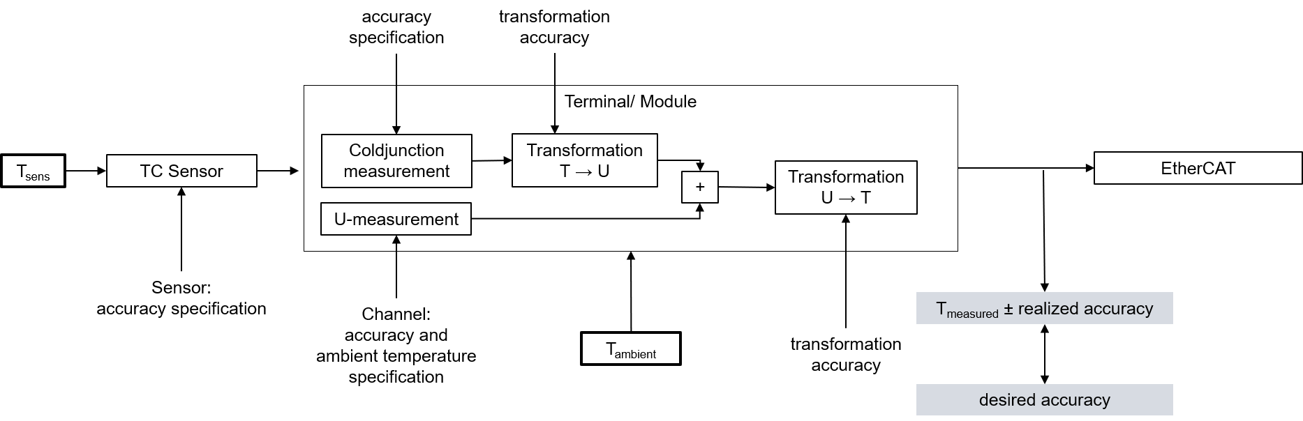
When measuring a temperature, there are various factors influencing the accuracy, from which the total inaccuracy (total uncertainty) is then derived.
Uncertainty of the voltage measurement
First and foremost, measuring a temperature with thermocouples is not based on an actual temperature measurement, but a voltage measurement with subsequent conversion into a temperature. The accuracy of the voltage measurement is therefore the basis for the accuracy of the temperature determination. Since a change of 1 °C at the sensor causes a change in the single-digit µV range, depending on the thermocouple type, even a small uncertainty of the voltage measurement has a large influence on the final result.
Uncertainty of the temperature conversion
The conversion of the measured voltage into a temperature is carried out during evaluation either by means of value tables from the characteristic voltage/temperature curve of a thermocouple type or by approximation based on a polynomial. Due to the non-linearity of the characteristic voltage/temperature curve, both options are only approximations of the actual values, so that the conversion results in a further (small) uncertainty component from the transformation.
Uncertainty of the cold junction evaluation
Cold junction compensation in thermocouple measuring devices must be carried out at the transition from the thermocouple to the copper contacts of the electronics. However, in many cases the temperature at this point cannot be measured directly for mechanical reasons. In this case the temperature of the cold junction has to be approximated at a distance of a few millimeters or through an average value of the housing temperatures. Since the exact value cannot be determined in this way, this results in further uncertainty.
Uncertainty of the sensor
The three factors influencing the uncertainty referred to above relate to the uncertainties in the evaluation of the thermocouples. The accuracy of the thermocouple itself is another factor and must also be taken into account.
Since temperature measurement with thermocouples is actually a voltage measurement and the thermocouples have a non-linear characteristic voltage/temperature curve, it is not possible to simply add up the individual temperature uncertainties to obtain the total uncertainty. To calculate the total uncertainty, all temperature values must be converted into the corresponding voltage value of the respective thermocouple type. When the temperatures are added together an error occurs, as described in the example in the chapter on "Determination of the absolute temperature".
The following diagram shows an example of an analysis of the uncertainties associated with the evaluation of a thermocouple for an EL331x thermocouple terminal with internal cold junction compensation and conversion of the voltage into a temperature via a second degree polynomial. The diagram does not take into account the uncertainty of the thermocouple itself, which is an additional factor!
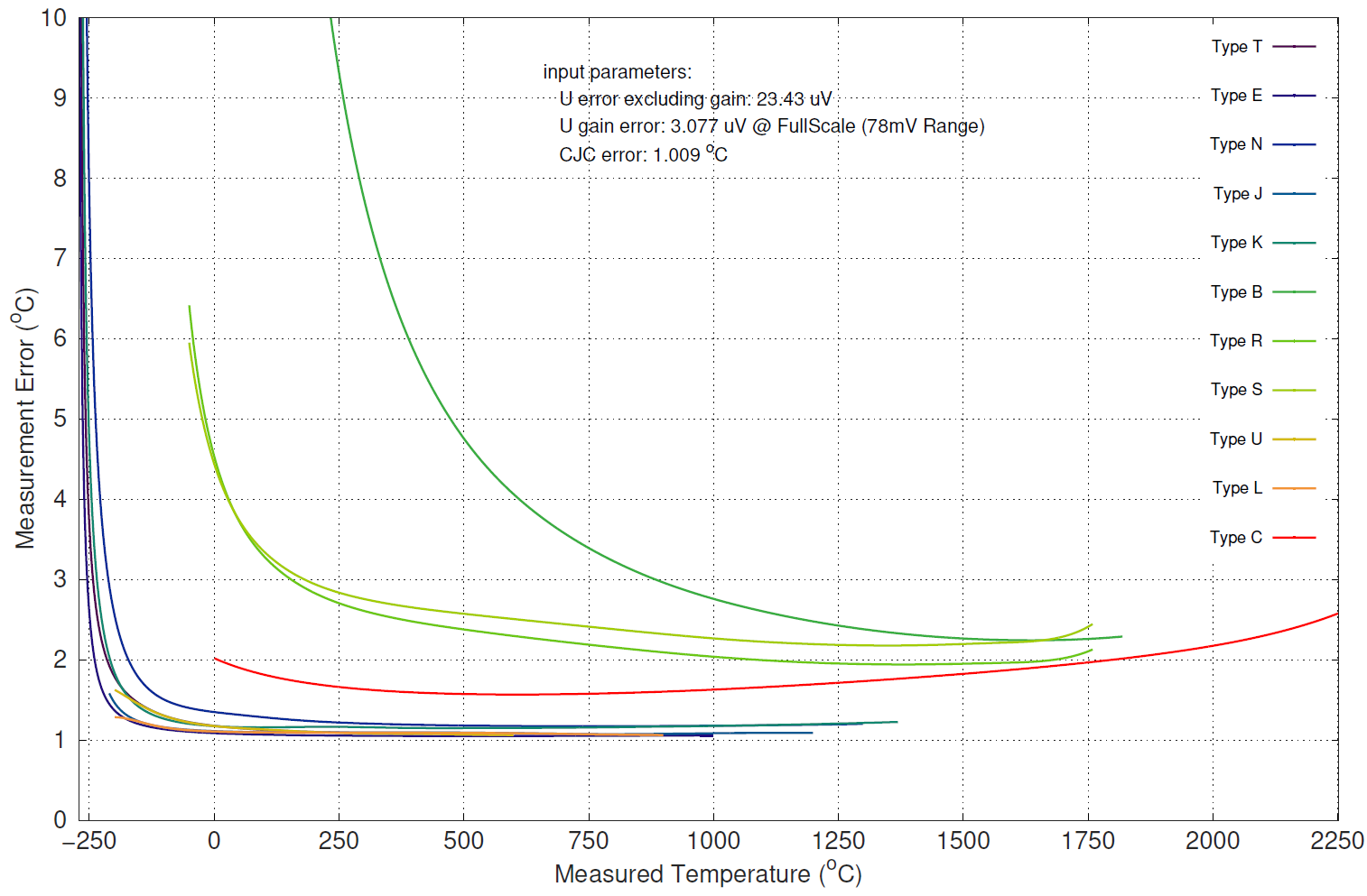
It is clear from the diagram that the uncertainty of the measured temperature depends on the temperature to be measured. Especially in the lower temperature range, where there is a strong non-linearity of voltage and temperature, the uncertainty of the temperature measurement increases significantly.
Beckhoff offers several products for the evaluation of thermocouples, including
- EL331x-0000: EtherCAT terminal, 1/2/4/8 channel analog input, temperature, thermocouple, 16 bit
- EL3314-0002: EtherCAT terminal, 4 channel analog input, temperature, thermocouple, 24 bit, electrically isolated
- EL3314-0010: EtherCAT terminal, 4 channel analog input, temperature, thermocouple, 24 bit, high-precision
- EL3314-0030: EtherCAT terminal, 4 channel analog input, temperature, thermocouple, 24 bit, high-precision, external calibrated
- EL3314-0090: EtherCAT terminal, 4 channel analog input, temperature, thermocouple, 16 bit, TwinSAFE SC
- ELM370x-xxxx: EtherCAT terminal, 2/4 channel analog input, multi-functional, 24 bit, 10 ksps
- ELM334x-xxxx: EtherCAT measurement technology series, thermocouple input, mini thermocouple connector
- EP3314-0002: EtherCAT Box, 4 channel analog input, temperature, thermocouple, 16 bit, M12
- EPP3314-0002: EtherCAT P Box, 4 channel analog input, temperature, thermocouple, 16 bit, M12
- KL331x: bus terminal, 1/2/4 channel analog input, temperature, thermocouple, 16 bit
- EJ3318: EtherCAT plug-in module, 8 channel analog input, temperature, thermocouple, 16 bit
The current overview can be found at www.beckhoff.com