Limit 1 and Limit 2
Limit 1 ad Limit 2, index 0x80n0:13, index 0x80n0:14
If the limits of the values that can be entered in indices 0x80n0:13 and 0x80n0:14 are violated, the bits in indices 0x60n0:03 and 0x60n0:05 are set accordingly (see sample below). The indices 0x80n0:07 or 0x80n0:08 serve to activate the limit value monitoring.
Output limit n (2-bit):
- 0: not active
- 1: Value < limit value
- 2: Value > limit value
- 3: Value = limit value
 | Limit evaluation The limit evaluation assumes a signed representation. The conversion to the desired representation (index 0x80n0:02) only takes place after the limit evaluation. |
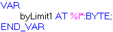
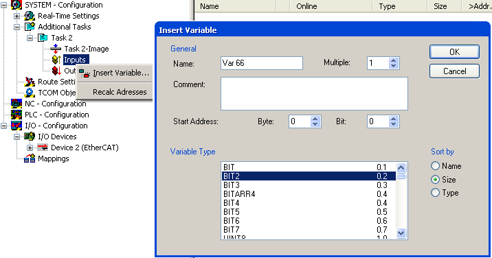
| Linking in the PLC with 2-bit values
|
Sample
Channel 1; Limit 1 and Limit 2 enabled, Limit 1 = 2.8 V, Limit 2 = 7.4 V, representation: signed integer
Entry in index (Limit 1): 0x8000:13
(2.8 V / 10 V) x 216 / 2 - 1 = 9,174dec
Entry in index (Limit 2): 0x8000:14
(7.4 V / 10 V) x 216 / 2 - 1 = 24,247dec
Output:
Input channel 1 | Index 0x6000:03 | Index 60x6000:05 |
|---|---|---|
1.8 V | 0x01hex, (Limit 1, limit value undershot) | 0x01hex, (Limit 2, limit value undershot) |
2.8 V | 0x03hex, (Limit 1, limit value reached) | 0x01hex, (Limit 2, limit value undershot) |
4.2 V | 0x02hex, (Limit 1, limit value exceeded) | 0x01hex, (Limit 2, limit value undershot) |
8.5 V | 0x02hex, (Limit 1, limit value exceeded) | 0x02hex, (Limit 2, limit value exceeded) |
Swap Limit index 0x80n0:0E
The limit function can be inverted by SwapLimitBits in index 0x80n0:0E.
Output Limit n (2-bit):
SwapLimitBits setting | Value |
|---|---|
FALSE (default setting) |
|
TRUE |
|