Tare
In the application, it can be helpful to set the display value to zero with an unloaded sensor. In weighing technology, this is known as the tare process or “relative measurement”. This means that the offset component of the unloaded sensor (in this case a scale) is already subtracted by the measuring device.
Note: When using tare, the value output in the channel is shifted, which leads to a restriction of the dynamic range in the positive or negative direction. If the channel can measure 0…10 V electrically, for example, and is tared (zeroed) at 8 V, only +2/-8 V of the measuring range remains.
To avoid reaching the INT16 limits, the use of Real32 PDOs is strongly recommended when using tare.
The tare function works as follows:
1. Tare start
Tare can be triggered in the same way by
- PDO: Tare bit in the “AI.Control” PDO
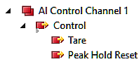
The controller can then trigger taring by changing the tare bit from 0 to 1.
- or via CoE command “Save tare” Request = 0x313n to index 0xFB00: 01 (Channel 1: n = 0, Channel 2: n = 1, ...)
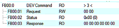
During command execution, “Status” 255 “busy”; is displayed in index 0xFB00:02, "0" means “successful completion”.
The firmware responds to an unknown command with

2. Measurement
The device now calculates an average value over 400 measured values; the duration of the process therefore depends on the conversion rate of the channel (see filter setting). During these approx. 250 ms, the electrical sensor signal should be stable. In some cases, it is recommended that the tare process be supported with a strongly attenuating low-pass filter (see chapter “Filter1”). After the tare process, the filter can be opened again.
During this time, PDO “AI Status.Tare Active” = FALSE
3. Calculation
Then
- The tare value is subtracted from the measured value and the measured value jumps once at this point.
- The determined tare value is displayed in CoE 0x90n0:1A.
- PDO “AI Status.Tare Active” = TRUE indicates that a tare value is being applied.
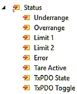
The tare value is stored temporarily in the channel and is not secured against power failure. If it is to be saved permanently and thus secured against power failure, the request 0x318n must be sent to index 0xFB00:01 (channel 1: n = 0, channel 2: n = 1, ...).
4. Reset
Tare is reset (“zeroed”)
- by an interface change
- or by de-energizing the device [(Re-)Power-Cycle], unless the tare value has not been stored secured against power failure; see above.
- or the EtherCAT status BOOTSTRAP
- or the CoE command “Tare Reset” Request = 0x314n to Index 0xFB00: 01 (Channel 1: n = 0, Channel 2: n = 1,…)
During command execution, “Status” 255 “busy” is displayed in index 0xFB00:02, "0" means “successful completion”.
The firmware responds to an unknown command with
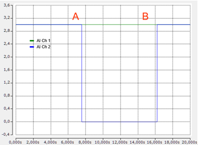
At (A), “Control.Tare” is set to 1 on Channel 2 (and the bit is then reset); the tare value is displayed in the CoE:

As expected, the measured value goes to ~0.
At (B), tare is deleted again by command. Channel 1 runs without tare for comparison.
Optional: Disable tare.
If you want to disable the tare function and then re-enable it without recalculating, you can select the “Disable Tare” option in the control PDO. As long as this bit is enabled, the measured value is not offset by the tare value. If this bit is reset to 0, the old tare value is reactivated without a new calculation.