Basic Function Principles
The EPP1518-0002 has 8 digital inputs. Of these, inputs 1, 2 and 3 as well as 5, 6 and 7 can each be used for one counter. The states of the individual inputs are always illustrated in the process image, irrespective of their use.
Input | M12 socket | Properties |
|---|---|---|
1 | X01, Pin 4 | Digital input or counter input 1 |
2 | X02, Pin 2 | Digital input or Gate 1 |
3 | X03, Pin 4 | Digital input or Up/Down 1 |
4 | X04, Pin 2 | Digital input |
5 | X05, Pin 4 | Digital input or counter input 2 |
6 | X06, Pin 2 | Digital input or Gate 2 |
7 | X07, Pin 4 | Digital input or Up/Down 2 |
8 | X08, Pin 2 | Digital input |
Operation modes
Three operation modes are available. The setting takes place by selecting the PDOs in the Sync-Manager:
Operation mode | Number of | Number of | Properties |
|---|---|---|---|
2 up/down counters (32-bit) | 2 | 2 | Single pulses are counted at the counter inputs. |
2 up/down counters (32-bit) | 1 | 5 | |
8 digital inputs, no counter | - | 8 | digital inputs: |
The GATE and Up/Down inputs can be converted to standard inputs.
Counting mode
The following settings for GATE and Up/Down can be combined and apply independently to each counter.
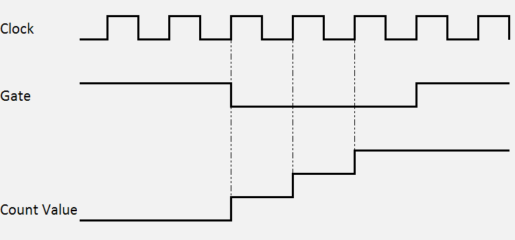
Counting mode with standard setting (up counter)
In the delivery state the Counter Value is incremented on each rising edge. The count direction is up.
The counter is disabled by applying a high level to the GATE input or by setting the Inhibit Counters bit.
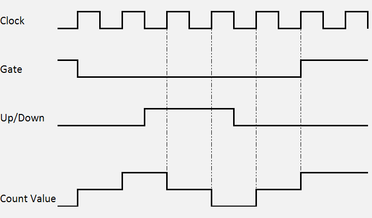
Counting mode with reversed count direction (down counter)
The count direction is changed by applying a high level to the Up/Down input or by setting the CoE object 0x80x0:04 Count down. The count direction is down.
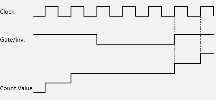
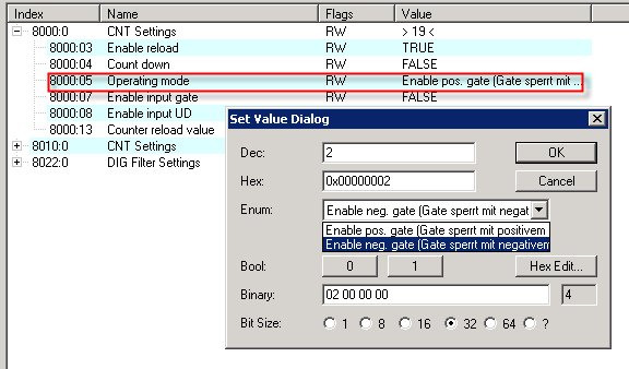
Counting mode with inverted (negated) GATE input
In the default setting the counter is disabled by applying a high level to the GATE input or by setting the Inhibit Counters bit
Setting the CoE object 0x80x0:05 Enable input gate activates the counter if GATE is set and deactivates it if GATE is not set.