Technology
The following figure shows an example of a voltage curve that illustrates the operation of EP9576-1032. The upper diagram shows the voltage UP in mV, the lower diagram shows the activity of the chopper.
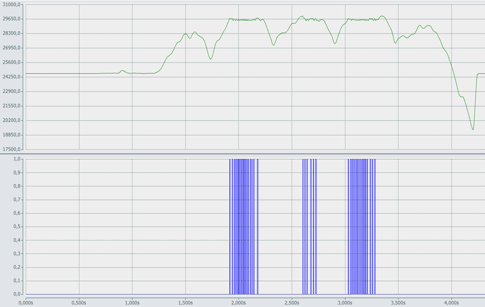
In this example, a motor output stage is supplied with UP = 24 V. The overvoltage limit is set to 28 V.
Electrical energy is generated when the motor brakes or when the motor shaft is moved by an external torque. The voltage UP increases.
If UP exceeds the overvoltage limit, the brake chopper is switched on. The brake chopper controls the current through the braking resistor. In the braking resistor the excess energy is dissipated and converted to heat. The voltage UP drops again.