IO-Link
Task
Connection of an IO-Link sensor to EP9300-0022.
Configuration of the process data
Each IO-Link device is added as a submodule. For each IO-Link device a submodule is used. The process data size of the submodule must always be equal to or greater than that of the IO-Link device and must not be less.
If not all IO-Link channels are used, empty channels should be entered. For example, if sensors are only connected to inputs 2 and 4 of the IO-Link master, while inputs 1 and 3 are unused, first enter an empty channel as submodule, then the sensor at input 2, then another empty channel and finally the sensor at input 4. The first submodule used by the IO-Link master is a diagnostics module. This is always present when the EL6224/EP6224 is added. This submodule contains the status of all connected IO-Link devices. If the sensor is in IO-Link data exchange, this is indicated via the corresponding byte (0x03 means all OK).
Information on the status byte:
0x_0 = Port disabled
0x_1 = Port in std dig in
0x_2 = Port in std dig out
0x_3 = Port in communication OP
0x_4 = Port in communication COMSTOP / dig in Bit (only in std. IO Mode)
0x_8 = Process Data Invalid Bit
0x1_ = Watchdog detected
0x2_ = internal Error
0x3_ = invalid Device ID
0x4_ = invalid Vendor ID
0x5_ = invalid IO-Link Version
0x6_ = invalid Frame Capability
0x7_ = invalid Cycle Time
0x8_ = invalid PD in length
0x9_ = invalid PD out length
0xA_ = no Device detected
0xB_ = error PreOP/Data storage
Regarding the process data size of an IO-Link device, please refer to the documentation or consult the manufacturer.
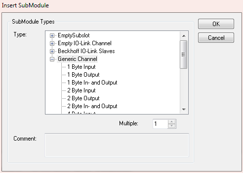
IO-Link devices from Beckhoff are automatically added with the required parameters. For devices from other manufacturers please use a generic channel and select the process data size.
Configuration of the IO-Link device
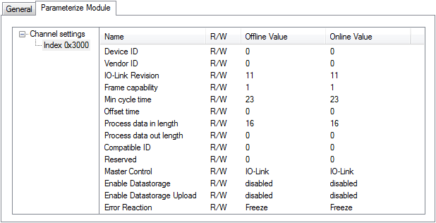
The minimum settings required for operating an IO-Link device are:
IO-Link version: Generally 1.1; enter 11
Frame capability: Generally 1
Min. cycle time: Generally 2.3 ms, i.e. 23
Process data in / Out length: Variable (number in bits), for a size of 2 bytes input enter 16 for "Process data in length".
Master control: set to IO-Link
All other settings are optional.
Reading/writing of parameters
Each IO-Link device has parameters, which can be read or written. The EK9300 does not support this function. I.e. no parameters can be read or written. The communication of the EK9300 with the IO-Link device is limited to the process data.
To access parameters of the IO-Link devices, use a Beckhoff controller (e.g. CX8093). Here you can read the IODD file (IO-Link device description) and read or write the sensor data via the PLC.