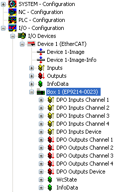
EP9214-0023 - Process image
|
|
The EP9214 has 4 x 16-bit status data of the four output channels DPO Inputs Channel n. Subsequently, a status word follows for the complete device DPO Inputs Device.
In the output section there are 4 x 16-bit output data of the four output channels DPO Outputs Channel n. An output word follows for the complete device DPO Outputs Device.
WcState and InfoData are standard EtherCAT system variables. |
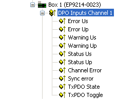
DPO Inputs Channel 1 to 4
|
|
The four channels each have status bits for displaying the current channel state: see Status LEDs
Channel Error: |
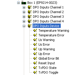
DPO Inputs Device
|
|
The EP9214 has 4 x 16-bit status data of the four output channels DPO Inputs Channel n.
Subsequently, a status word follows for the complete device DPO Inputs Device.
Channel Error: |
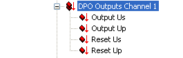
DPO Outputs Channel 1 to 4
|
|
The EP9214 has 4 x 16-bit output data of the four output channels DPO Outputs Channel n. Output Us: Reset Us: |
DPO Outputs Device
|
|
Subsequently, a status word follows for the complete device DPO outputs Device. Enable Control Via Fieldbus: Global Reset: |