Data stream
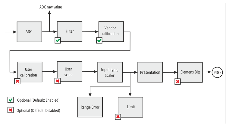
The following flow chart shows the data stream for the analog input.
Designation | CoE - Index | CoE - Name | Factory setting (default) | Meaning |
|---|---|---|---|---|
ADC raw value | 0x80AE:01 | ADC raw value |
| ADC raw value |
Filter | 0x80A0:06 | Enable filter | TRUE | Enable digital filter |
0x80A0:15 | Filter settings | 50 Hz FIR (2) | Select filter type | |
Vendor calibration | 0x80A0:0B | Enable vendor calibration | TRUE | Enable vendor calibration |
0x80AF:01 | Calibration offset | Parameters for the vendor calibration. These parameters are read-only and can only be changed by the vendor. | ||
User calibration | 0x80A0:0A | Enable user calibration | FALSE | Enable user calibration |
0x80A0:17 | User calibration offset | 0 | User calibration offset | |
0x80A0:18 | User calibration gain | 16384dec | User calibration gain | |
User scale | 0x80A0:01 | Enable user scale | FALSE | Enable user scale |
0x80A0:11 | User scale offset | 0 | User scale offset | |
0x80A0:12 | User scale gain | 65535 | User scale gain | |
Input type, Scaler | 0x80AD:01 | Input type | V ±10 V (2) | Selection of the measuring range |
0x80AD:12 | Scaler | Extended Range (0) | Select scaling type: | |
Range Error | 0x80AD:17 | Low Range Error | -32768dec | Lower error threshold, |
0x80AD:18 | High Range Error | 32768dec | Upper error threshold, | |
Limit | 0x80A0:07 | Enable Limit 1 | FALSE | Enable limit value monitoring for "Limit 1" |
0x80A0:08 | Enable Limit 2 | FALSE | Enable limit value monitoring for "Limit 2" | |
0x80A0:13 | Limit 1 | 0 | "Limit 1" for limit value monitoring | |
0x80A0:14 | Limit 2 | 0 | "Limit 2" for limit value monitoring | |
0x80A0:0E | Swap Limit bits | FALSE | Invert limit function | |
Presentation | 0x80A0:02 | Presentation | Signed (0) | Select data format of the measured values |
Siemens bits | 0x80A0:05 | Siemens bits | FALSE | Select Siemens output format |