Process image
|
| |
| Diagnosis. See chapter Further error diagnosis. | |
| ||
| Status bytes of the IO-Link ports. See chapter Status of the IO-Link ports. | |
| ||
| Process data of the IO-Link device at port 1 (connector X03) | |
| ||
| Process data of the IO-Link device at port 2 (connector X04) | |
| ||
| Process data of the IO-Link device at port 3 (connector X07) | |
| ||
| Process data of the IO-Link device at port 4 (connector X08) | |
| ||
| Digital inputs. | |
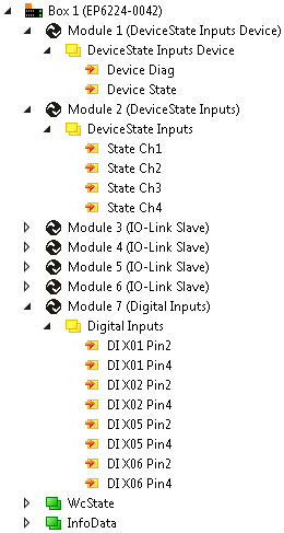

Assignment of connectors, ports and process data
Connector | IO-Link port | Process data | Status variable |
|---|---|---|---|
X03 | 1 |
|
|
X04 | 2 |
|
|
X07 | 3 |
|
|
X08 | 4 |
|
|

1) The modules "Module 3" to "Module 6" only exist in the process data if the corresponding IO-Link ports have been configured.