Process image
|
| |
| Diagnostics. See chapter Further error diagnosis. | |
| ||
| Status bytes of the IO-Link ports. See chapter Status of the IO-Link ports. | |
| ||
| Process data of the IO-Link device at X01 | |
| ||
| Process data of the IO-Link device at X02 | |
| ||
| Process data of the IO-Link device at X03 | |
| ||
| Process data of the IO-Link device at X04 | |
| ||
| Process data of the IO-Link device at X05 | |
| ||
| Process data of the IO-Link device at X06 | |
| ||
| Process data of the IO-Link device at X07 | |
| ||
| Process data of the IO-Link device at X08 | |
| ||
| Digital inputs. | |
| ||
| Digital outputs. | |
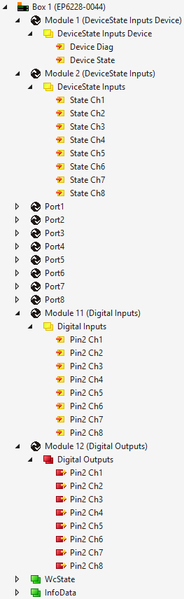

1) The modules "Port 1" to "Port 8" only exist in the process data if the corresponding IO-Link ports have been configured.