Filter
FIR and IIR filter
The box is equipped with a digital filter which, depending on its settings, can adopt the characteristics of a Finite Impulse Response filter (FIR filter), or an Infinite Impulse Response filter (IIR filter). The filter can also be deactivated.
 | The filter characteristics are set via index 0x8020:15 The filter frequencies are set centrally for all channels of the box via index 0x8020:15 (channel 1). The corresponding indices 0x80n0:15 of the other channels have no parameterization function. |
FIR filter
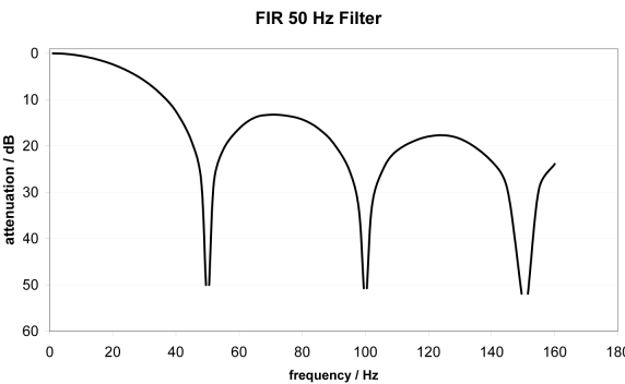
The filter works as a notch filter and determines the conversion time of the box. It is parameterized via the index 0x8020:15. The higher the filter frequency, the faster the conversion time. A 50 Hz and a 60 Hz filter are available.
Notch filter means that the filter has zeros (notches) in the frequency response at the filter frequency and multiples thereof, i.e. it attenuates the amplitude at these frequencies.
The FIR filter functions as a non-recursive filter, which can be adjusted by the parameterization of the object 0x8020:15.
Filter data FIR filter (1-4-channel boxes)
Filter | Attenuation | Limit frequency (-3 dB) |
|---|---|---|
50 Hz FIR | > 50 dB | 22 Hz |
60 Hz FIR | > 40 dB | 26 Hz |
Filter data FIR filter (8-channel boxes)
Filter | Attenuation | Limit frequency (-3 dB) |
|---|---|---|
50 Hz FIR | > 50 dB | 23 Hz |
60 Hz FIR | > 50 dB | 27 Hz |
IIR filter
The filter with IIR characteristics is a discrete time, linear, time invariant filter that can be set to eight levels (level 1 = weak recursive filter, up to level 8 = strong recursive filter).
The IIR can be understood to be a moving average value calculation after a low-pass filter.
By means of the synchronization mode FreeRun, the IIR filter works with an internal cycle time of 500 µs (1, 2 or 4 channels) or 1 ms (8 channels).
Filter data for IIR filter
IIR filter | Limit frequency with internal box cycle time 1 ms (-3 dB) |
|---|---|
IIR 1 | 168 Hz |
IIR 2 | 88 Hz |
IIR 3 | 43 Hz |
IIR 4 | 21 Hz |
IIR 5 | 10.5 Hz |
IIR 6 | 5.2 Hz |
IIR 7 | 2.5 Hz |
IIR 8 | 1.2 Hz |
Conversion time & FIR and IIR filters, index 0x80n0:06
The typical conversion time and trigger mode depend on
- the selected filter setting (default: 50 Hz)
- the setting in the CoE register 0x1C33:01
- by manual parameterization in the System Manager. CAUTION: Enter any changes made in the StartUp list!
- by the StartUp list as an automatic parameter download during the EtherCAT start phase. CAUTION: Entries are implemented only after activation of the configuration!
The conversion time is the time interval in which the box makes a new measured value available. A new measured value is displayed by toggling “TxPDO Toggle” (index 0x60n0:10).